Variable
name
Data
type
Default
value
Description
VAR_IN_OUT
Output AXIS_REF_ISD51x Reference to the axis/
signal output.
See
chapter 6.5.4.1 AXIS_REF_IS
D51x.
VAR_INPUT
Enable BOOL FALSE Control the digital CAM
switching functionality.
Enable-
Switches
BOOL FALSE Enables/disables the
digital CAM switching
functionality.
VAR_OUTPUT
InOperation BOOL The digital CAM switching
functionality is enabled.
Busy BOOL The function block is not
nished and new output
values are to be expected.
Error BOOL An error has occurred
within the function block.
ErrorInfo DD_ERROR_ISD51x Error identication and
instance identier.
See chapter 6.5.2.3 Error
Indication.
Table 6.34 DD_DigitalCamSwitch_ISD51x
6.5.4.31 DD_ProduceGuideValue_ISD51x
This function block simulates a guide value inside the PLC.
It must be called in every cycle to update the guide values.
If Enable is TRUE, the guide values are updated and the
current input values are used. Only linear ramps are used
for the guide value calculation. For the inputs GuideAccel-
eration and GuideDeceleration, a value of 0 is not allowed
and leads to an error.
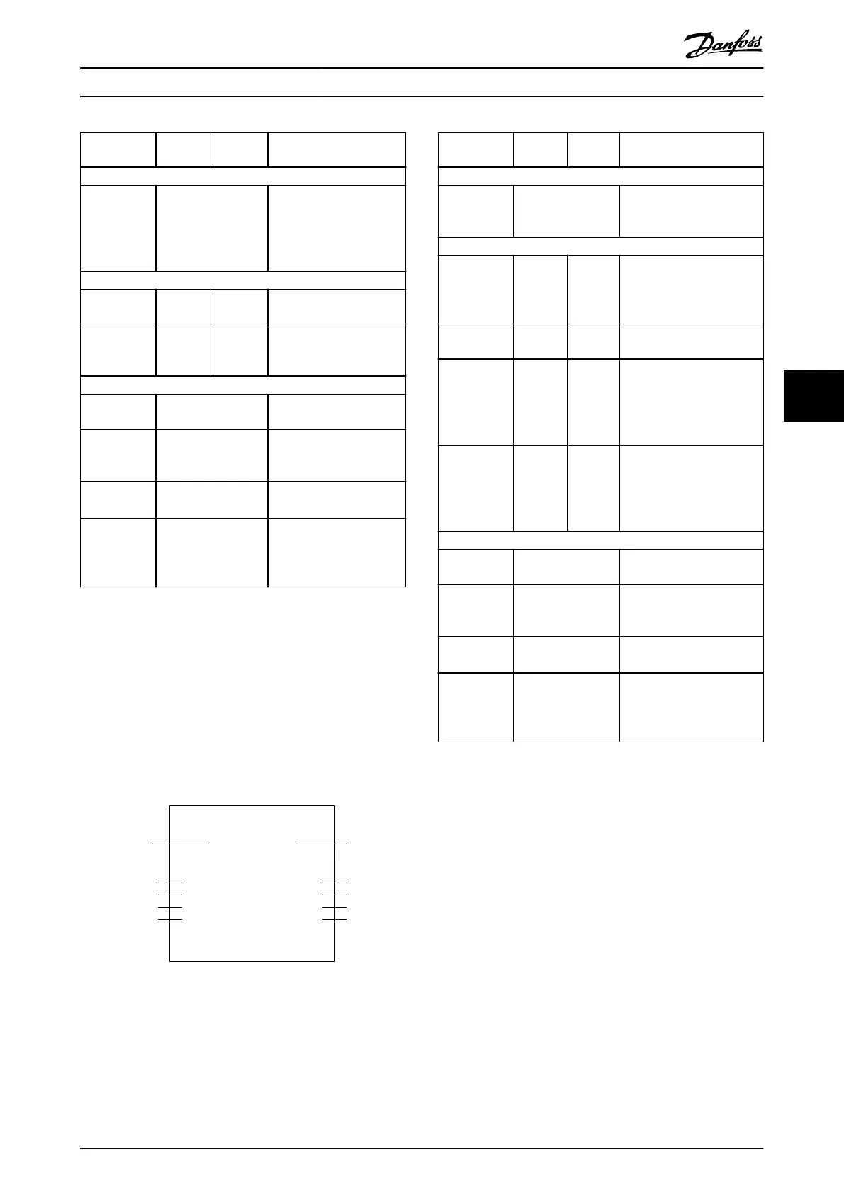
DD_ProduceGuideValue_ISD51x
GuideValueProducer
EnableBOOL
GUIDE_VALUE_-
REF_ISD51x
GuideVelocityREAL
GuideAccelerationREAL
GuideDecelerationREAL
BOOLInGuideVelocity
BOOLBusy
DD_ERROR_-
ISD51x
ErrorInfo
BOOLError
130BE266.10
Illustration 6.57 DD_ProduceGuideValue_ISD51x
Variable
name
Data
type
Default
value
Description
VAR_IN_OUT
GuideValue-
Producer
GUIDE_VALUE_REF_I
SD51x
Reference to the guide
value producer.
See Table 6.54.
VAR_INPUT
Enable BOOL FALSE Updates the guide value
producer if Enable is TRUE.
If Enable is FALSE, the guide
value stops immediately.
GuideVelocity REAL 0.0 Velocity of the guide value
[rps].
GuideAccel-
eration
REAL 0.0 Acceleration value used
while increasing the
velocity of the guide value.
Only positive values are
allowed [rps/s].
GuideDecel-
eration
REAL 0.0 Deceleration value used
while decreasing the
velocity of the guide value.
Only positive values are
allowed [rps/s].
VAR_OUTPUT
InGuideVe-
locity
BOOL Commanded guide velocity
reached.
Busy BOOL The function block is not
nished and new output
values are to be expected.
Error BOOL An error has occurred
within the function block.
ErrorInfo DD_ERROR_ISD51x Error identication and
instance identier.
See chapter 6.5.2.3 Error
Indication.
Table 6.35 DD_ProduceGuideValue_ISD51x
6.5.5 Drive – Motion
6.5.5.1 MC_Home_ISD51x
This function block commands the axis to set its position
to the input value given. It enables the execution of
dierent homing modes. Depending on the selected Mode,
several input parameters must be set (see Table 6.38). Also,
the preconditions of this mode must be met. For detailed
descriptions of the Homing modes, see
chapter 2.4.4 Homing Mode.
The time limit is supervised by the PLC. Use function block
MC_Stop_ISD51x (chapter 6.5.5.2 MC_Stop_ISD51x) to abort
an active homing procedure.
It can take some time until the homing procedure starts.
Programming Programming Guide
MG36D102 Danfoss A/S © 01/2017 All rights reserved. 197
6
6

 Loading...


