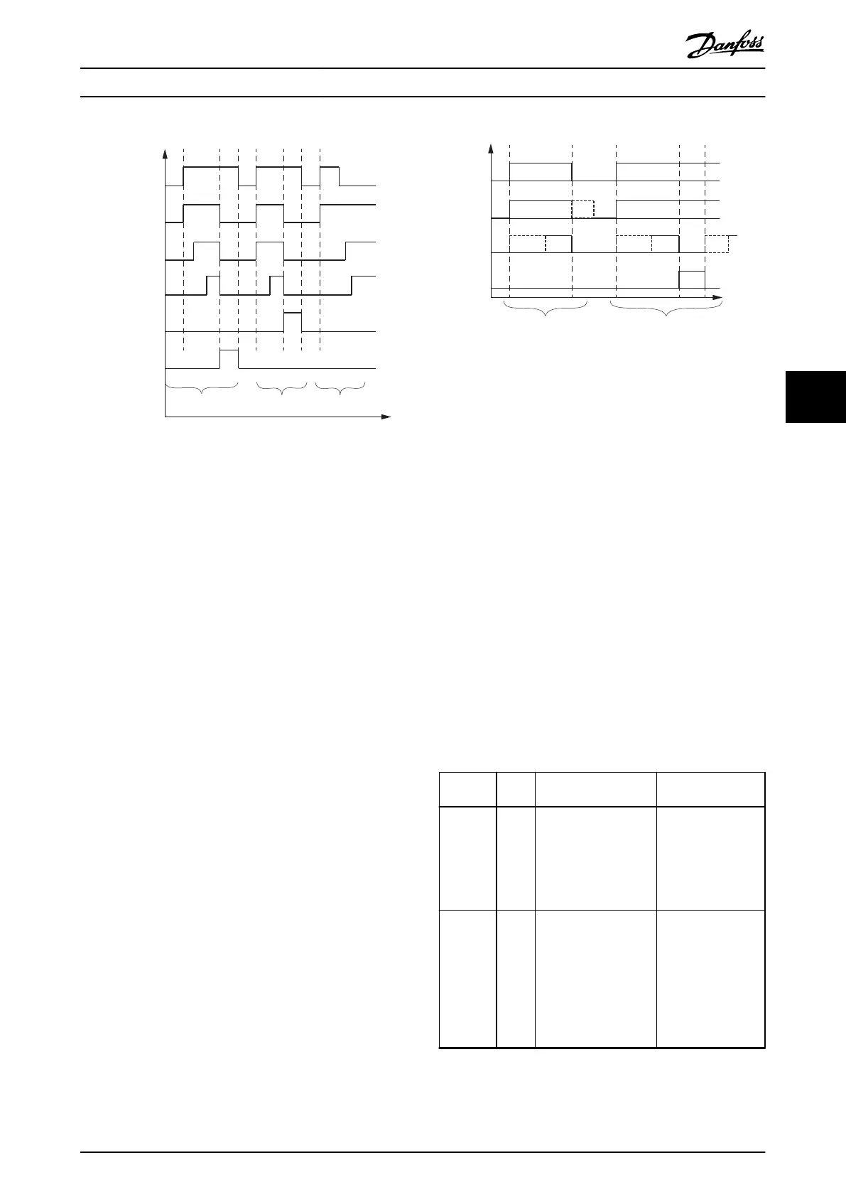
Execute
Busy
Active
InXxx
Error
CommandAborted
130BE944.10
Case1 Case2 Case3
Illustration 6.20 Behavior of the Execute/Inxxx Style Function
Blocks
CommandAborted
CommandAborted is TRUE when a commanded motion is
interrupted by another motion command. The reset-
behavior of CommandAborted is like that of the output
Done. When CommandAborted becomes TRUE, the other
output signals are reset (see case 1 in Illustration 6.19 and
Illustration 6.20).
6.5.2.2 Function Blocks with Enable Input
The parameters are used with the rising edge of the Enable
input and can be modied continuously.
Output exclusivity
The outputs Valid and Error are mutually exclusive,
meaning that only 1 of them can be TRUE on 1 instance of
a function block at the same time. The outputs Valid, Busy,
Error, and ErrorInfo are reset with the falling edge of Enable
as soon as possible, depending on the cycle times of the
PLC program and the point where Enable is reset.
Busy
The output Busy reects that the function block is working
and new output values can be expected. Busy is set at the
rising edge of Enable and stays set while the function
block is performing an action. Keep the function block in
the active loop of the application program for at least as
long as Busy is TRUE, because the outputs may still change.
Enable
Busy
Valid
Error
* *
*
*
130BE945.10
Case1 Case2
Illustration 6.21 Behavior of the Enable Style Function Blocks
* Can take some time, depending on the functionality and the
internal state
Valid
The Valid output is TRUE if a valid output value is available,
and the Enable input is TRUE (see case 1 in Illustration 6.21).
The relevant output value can be refreshed if the input
Enable is TRUE. If there is a function block error, the output
is not valid (Valid is set to FALSE). When the error condition
disappears, the values reappear and the output Valid is set
again (see case 2 in Illustration 6.21).
6.5.2.3 Error Indication
All function blocks have 2 outputs that deal with errors
that can occur while executing functionality. These outputs
are dened as:
•
Error: Rising edge of Error informs that an error
occurred during the execution of the function
block.
•
ErrorInfo: Structure of DD_ERROR_ISD51x, which
consists of the elements detailed in Table 6.1.
Variable
name
Data
type
Default value Description
ErrorID WORD ISD51x_ERR_NO_ERROR Contains unique
error identication.
The error constant
denitions are listed
in the constants list
FB_ErrorConstants.
InstanceID UDINT 0 Contains unique
identier of the
function block
instance that caused
the error. Can be
used for central
error handling
within a PLC project.
Programming Programming Guide
MG36D102 Danfoss A/S © 01/2017 All rights reserved. 175
6
6

 Loading...


