7.2.1.4 Controlword in Homing Mode
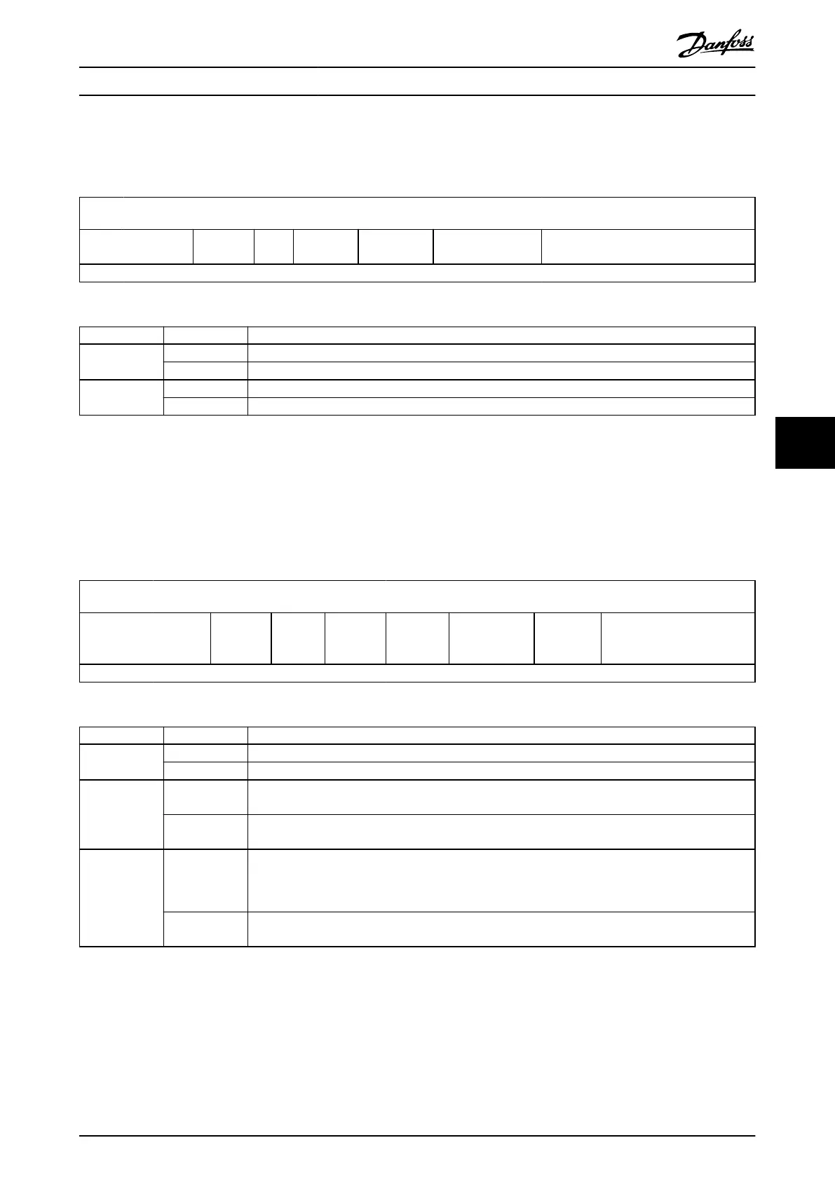
Table 7.13 shows the structure of the Controlword. Table 7.14 denes the values for bits 4 and 8 of the Controlword.
15 10 9 8 7 6 4 3 0
See Table 7.2
Reserved
(0)
Halt
See
Table 7.2
Reserved (0)
Homing operation
start
See Table 7.2
MSB LSB
Table 7.13 Controlword in Homing Mode
Bit Value Denition
4 0 Do not start homing procedure.
1 Start or continue homing procedure.
8 0 Enable bit 4.
1 Stop axis according to halt option code (see chapter 7.20.7 Parameter 50-47: Halt Option Code (0x605D)).
Table 7.14 Denition of Bits 4 and 8
7.2.1.5 Controlword in CAM Mode
Table 7.15 shows the structure of the Controlword. The rising edge of bit 4 starts the CAM prole activation request.
Table 7.16 denes the values for bits 5, 6, and 9 of the Controlword. It is assumed that the activation request of a CAM is
edge-triggered 0→1, otherwise the axis has no clear point in time when to activate a new CAM
prole, or to reactivate a
CAM prole without any content changes.
15
10 9 8 7 6 5 4 3 0
See Table 7.2
Use blend
distance
Reserved
(0)
See
Table 7.2
Control
parameter
source
Change CAM
immediately
New CAM See Table 7.2
MSB LSB
Table 7.15 Controlword in CAM Mode
Bit Value Denition
5 0 Currently active CAM prole is nished rst (target reached).
1 Next CAM prole is started immediately.
6 0 Control parameter set selection uses the manufacturer-specic bit of the Controlword (bit 15). This is
default behavior as in other modes of operation.
1 Control parameter set selection is done automatically inside the CAM prole. The manufacturer-specic
bit of the Controlword (bit 15) for selection is ignored by the axis.
9 0 Automatically blend to the beginning of the new CAM:
•
Basic CAM: 1st data point
•
Advanced CAM: starting node
1 Uses value of object 0x380A (see chapter 7.14.11 Parameter: Minimum Blending Distance (0x380A)) as the
minimum length for blending to a new CAM.
Table 7.16 Denition of Bits 5, 6, and 9
Servo Drive Parameter Descr... Programming Guide
MG36D102 Danfoss A/S © 01/2017 All rights reserved. 235
7 7

 Loading...


