7.14.7 Parameter: CAM Prole Selector (0x3804)
This object indicates the selected CAM slave table. To activate a new CAM or reactivate an already processed one, write the
number of the required table to this object and start it by using the handshaking procedure described in
chapter 2.4.5.1 Activating a CAM prole.
If bits 13–15 are set, the real start of the CAM is delayed until the congured input is on. The behavior of the activation is
then as if the handshake is taking place at the occurrence of the (input) event. If the start of that CAM is Slave absolute, the
servo drive jumps to the correct position.
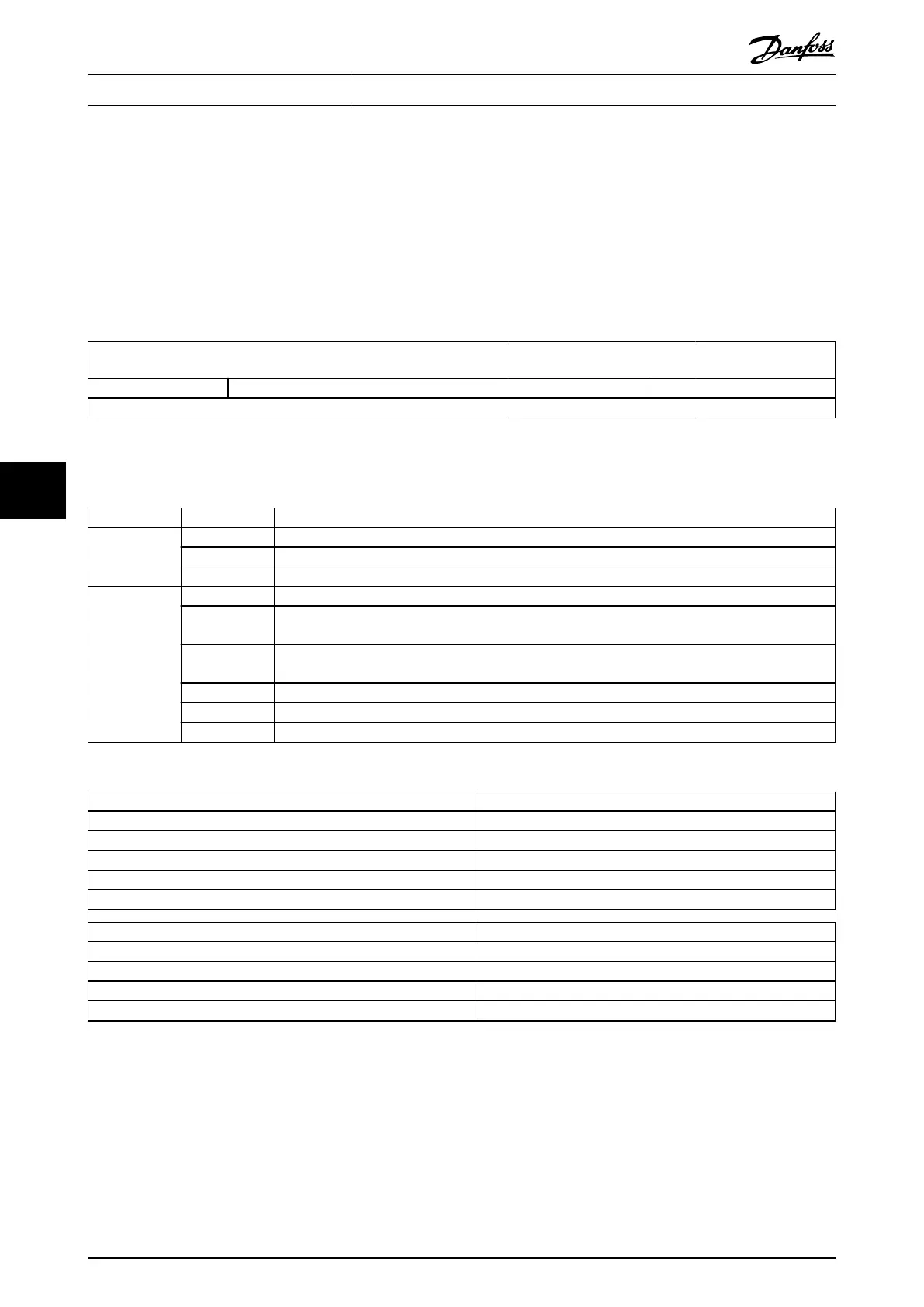
15 14 13 12 11 10 9 8 7 6 5 4 3 2 1 0
delay code reserved number of CAM prole
MSB LSB
Table 7.150 0x3804: CAM Slave Table Selector
The value range of the number of CAM prole is limited to 1–8 according to Table 7.149.
Bit Value Denition
0–3 0 Not allowed.
1–8 Selects the CAM prole to be activated.
9–15 Reserved.
13–15 0 Normal CAM activation behavior, independent of digital input signals.
1 Delayed activation of CAM: Processing of CAM is delayed until digital input 1 is on; input 2 is
irrelevant.
2 Delayed activation of CAM: Processing of CAM is delayed until digital input 2 is on; input 1 is
irrelevant.
3 Delayed activation of CAM: Processing of CAM is delayed until digital input 1 or digital input 2 is on.
4 Delayed activation of CAM: Processing of CAM is delayed until digital input 1 and digital input 2 is on.
5–7 Reserved.
Table 7.151 Denition of Bits of the CAM Slave Table Selector
Attribute Value
Index 0x3804
LCP parameter number –
Name CAM prole selector
Object code Var
Data type UNSIGNED16
Sub-index 0x00
Access Read/write
PDO mapping Optional
Value range See Table 7.151.
Default value 0
Table 7.152 0x3804: CAM Prole Selector
Servo Drive Parameter Descr...
VLT
®
Integrated Servo Drive ISD
®
510 System
302 Danfoss A/S © 01/2017 All rights reserved. MG36D102
77

 Loading...


