Name Description
Partial CAM
A CAM that is dened with the 1
st
data point not at guide value 0 or
last data point not at guide value 1
(or both). The CAM is only dened
on part of the guide value cycle.
Parts of the guide value are
“undened”. Not applicable for
advanced CAM.
P5
Polynomial of 5
th
degree.
End of prole Output signaling the end of the
CAM prole. For cyclic processing of
the CAM, it is displayed every time
the end of the CAM prole is
reached. This signal is only high for
1 eldbus cycle. For basic CAMs, the
end of prole is signaled at the last
data point. For advanced CAMs, the
end of prole is signaled at each
end node.
InSync Output InSync is high as long as the
slave follows the commanded CAM
prole.
Blending Blending occurs whenever the servo
drive automatically calculates a P5
when switching between CAMs, or
it is used to ll up the undened
parts in cyclic processing of CAMs.
Table 2.5 Terminology
2.4.5.1 Activating a CAM prole
Perform the following steps to activate a CAM prole:
1. Write the CAM data to 1 of the objects 0x3820–
0x3827: CAM data 1–8 (see
chapter 7.14.5 Parameters: CAM Data 1–8 (0x3820–
3827)).
2. Write the CAM conguration and activate the
CAM parsing to the corresponding object
0x3810–0x3817: CAM prole, sub-index 01 (see
chapter 7.14.4 Parameters: CAM Prole 1–8
(0x3810–0x3817)).
3. Check the CAM parsing state in objects 0x3810–
0x3817: CAM prole, sub-index 02 and 03 (see
chapter 7.14.4 Parameters: CAM Prole 1–8
(0x3810–0x3817)).
4. Write the number of the CAM and the delay code
that should be used into object 0x3804: CAM
prole selector (see chapter 7.14.7 Parameter: CAM
Prole Selector (0x3804).
5. Switch to CAM mode (this can also be done
earlier).
6. Perform handshaking to send the CAM activation
request.
To transfer a CAM prole, use function block MC_CamTable-
Select_ISD51x (see
chapter 6.5.6.1 MC_CamTableSelect_ISD51x).
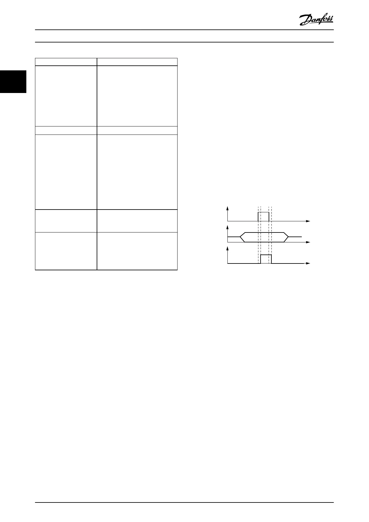
CAM prole activation request (Handshaking)
The activation of a CAM prole is controlled by the timing
of the New CAM bit in the Controlword, and the CAM ack
bit in the Statusword. After a CAM prole is transferred and
successfully parsed, the control device signals that the
CAM prole will be activated (CAM prole activation
request) by a rising edge of the New CAM bit in the
Controlword. The axis internally calculates all necessary
parameters and afterwards sets the CAM ack bit in the
Statusword to 1. With the CAM ack bit set to 0, the axis
signals its ability to accept new CAM proles. An example
is shown in Illustration 2.36. After activation of the CAM
prole, the CAM is not necessarily executed immediately.
This depends on the CAM conguration and the change
immediate bit in the Controlword.
New CAM
(Bit 4)
CAM
prole
selector
CAM ack
(Bit 12)
Illustration 2.36 Handshaking Procedure for CAM Prole
Activation
The CAM prole can also be activated using function block
MC_CamIn_ISD51x (see chapter 6.5.6.2 MC_CamIn_ISD51x).
The axis supports a set of 2 CAM proles numbers: a CAM
prole that is currently being processed, and a buered
prole.
If a CAM prole is still in progress and a new CAM prole
is validated by the new CAM (bit 4) in the Controlword, 2
methods of handling are supported:
•
The new CAM prole is activated immediately
(Change CAM immediately bit of the Controlword
is set to 1).
•
The currently active CAM prole is nished rst
and afterwards the new CAM prole is started
(Change CAM immediately bit of the Controlword
is set to 0).
When a new CAM prole is activated, all specic
parameters are activated at the start of the new prole
(this is the beginning of the blending). This can lead to
jumps in position and velocity, for example when using
dierent master scaling values.
Servo Drive Operation
VLT
®
Integrated Servo Drive ISD
®
510 System
40 Danfoss A/S © 01/2017 All rights reserved. MG36D102
22

 Loading...


