New CAM
(Bit 4)
selector
status
CAM ack
(Bit 12)
Change CAM
immediately
(Bit 5)
1
2 3 4
5
A B C D E
A A
B
B B B
CC
E
130BF185.10
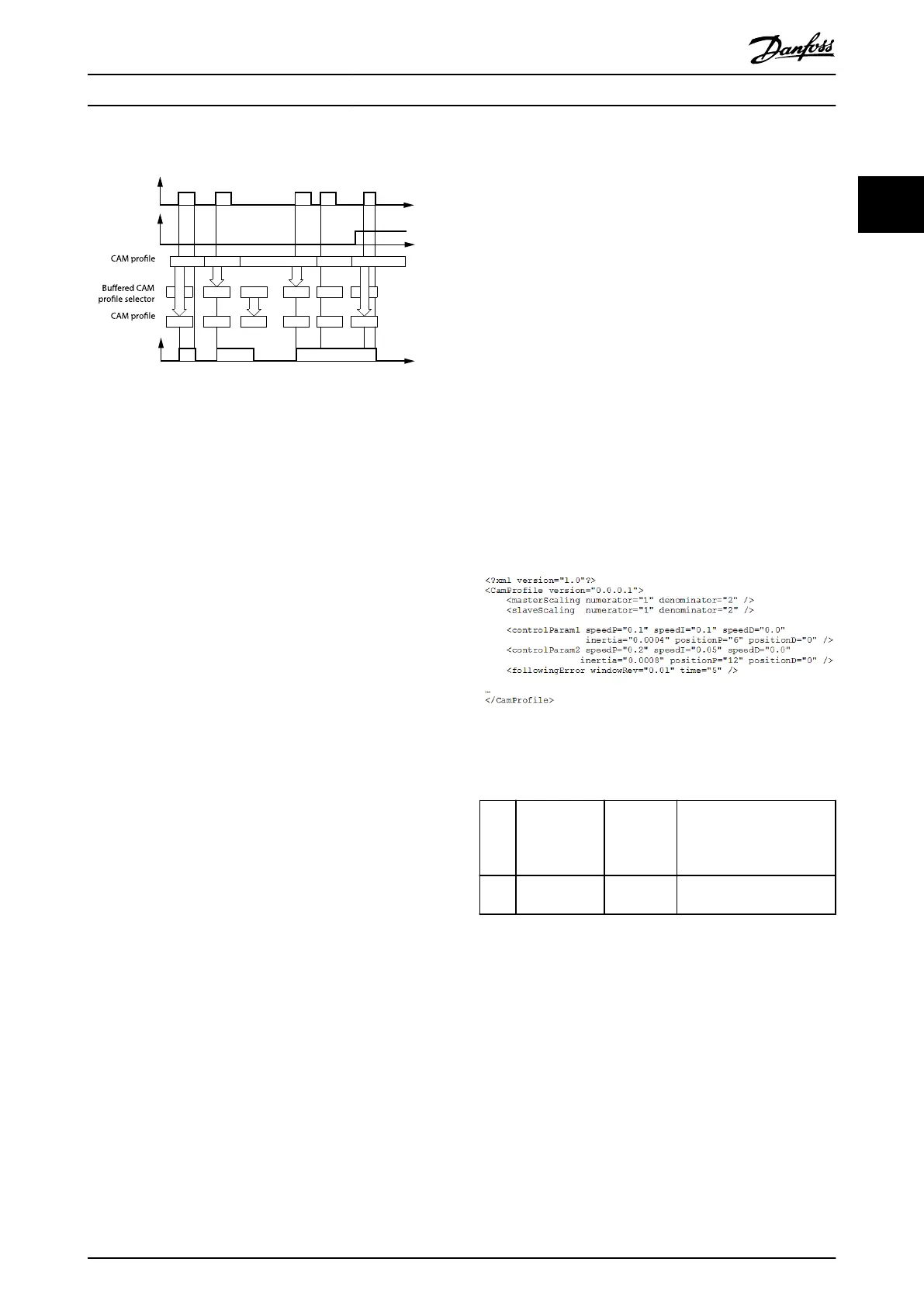
Illustration 2.37 CAM Prole Handling for 2 CAM Proles
New CAM prole numbers are buered in the buered
CAM prole selector as long as there is a free CAM prole
selector buer available in the axis. If no CAM is in
progress, the new CAM prole becomes active immediately
(case 1 in Illustration 2.37).
If a CAM prole is in progress, the new CAM prole
number is stored in the CAM prole buer (cases 2 and 3
in Illustration 2.37). If all prole number buers are busy
(CAM ack bit is 1), the reaction depends on the Change
CAM immediately bit. If the Change CAM immediately bit is
set to 0, the new CAM prole is rejected (case 4) with a
command error indication (Statusword). If the Change CAM
immediately bit is set to 1, the new CAM prole number is
processed immediately. The currently running CAM prole
is discarded (case 5 in Illustration 2.37).
The Buered CAM prole selector is not available as an
object for readout. There are cases where it is necessary to
do a compensation movement when switching between
CAMs. This movement is called blending and it is
calculated automatically by the servo drive. The blending
takes place using a polynomial of 5
th
degree.
2.4.5.2 CAM Conguration: Master
Absolute/Relative
If the master and slave positions are congured to be
absolute positions, it is necessary to have a synchroni-
zation movement that aligns the position at the point of
activation with the set-position of the prole. This is called
blending. For blending, a polynomial of 5
th
degree is used.
It is automatically calculated by the servo drive.
The blending can be inuenced using bit Use blend
distance. When set to 0, the blending is done to the 1
st
data point of a basic CAM, or the start node of an
advanced CAM. This distance can be very short, which
leads to high velocity or acceleration.
When a concrete blend distance is used, set the Use blend
distance bit. Then, the value given in the minimum
blending object 0x380A (see chapter 7.14.11 Parameter:
Minimum Blending Distance (0x380A)) is used to calculate a
synchronization movement within the axis. This distance
should be regarded as a minimum value, as there are
situations where the servo drive automatically enlarges this
distance (for example, if the end of the distance does not
lead to a point of a dened CAM, see Illustration 2.50).
When using non-cyclic CAM proles, the inuence of
Master relative versus Master absolute is only an oset in
guide value direction. This is dependent on the point of
activation of the CAM prole.
2.4.5.3 CAM Header Information
All parameters dened in this header information have
corresponding parameters in the object dictionary. These
objects are updated at the point of activation of the CAM.
If an element is not included in the header (which is
allowed for optional elements), the parameter in the object
dictionary remains unchanged. When leaving a CAM, the
values in the object dictionary persist; so they are not
switched back to their old values before the CAM
activation. The header information is the same for both
CAM types.
Illustration 2.38 CAM Header Information
Each le can only contain 1 CamProle element.
Attri
bute
Mandatory/
optional
(+default
value)
Value
range/
allowed
values
Description
Versi
on
O x.x.x.x Gives the version of the
CAM prole denition.
Table 2.6 Attribute for Element CamProle
The CamProle element contains an optional element
masterScaling which denes the length of a guide value
cycle. This parameter is used as scaling factor. If this
element is missing, the values from the object dictionary
are used (see chapter 7.8.4 Parameter: Guide Value Scaling
Factor (0x3808)).
Servo Drive Operation Programming Guide
MG36D102 Danfoss A/S © 01/2017 All rights reserved. 41
2 2

 Loading...


