Absolute master position, absolute slave position
Guide value
cycle
Rotor angle of axis
0 1 2
InSync
End of
prole
Active
CAM
CAM 2 CAM 3
Blending
Master absolute
Slave absolute
Change CAM imm=0
Use blend dist=0
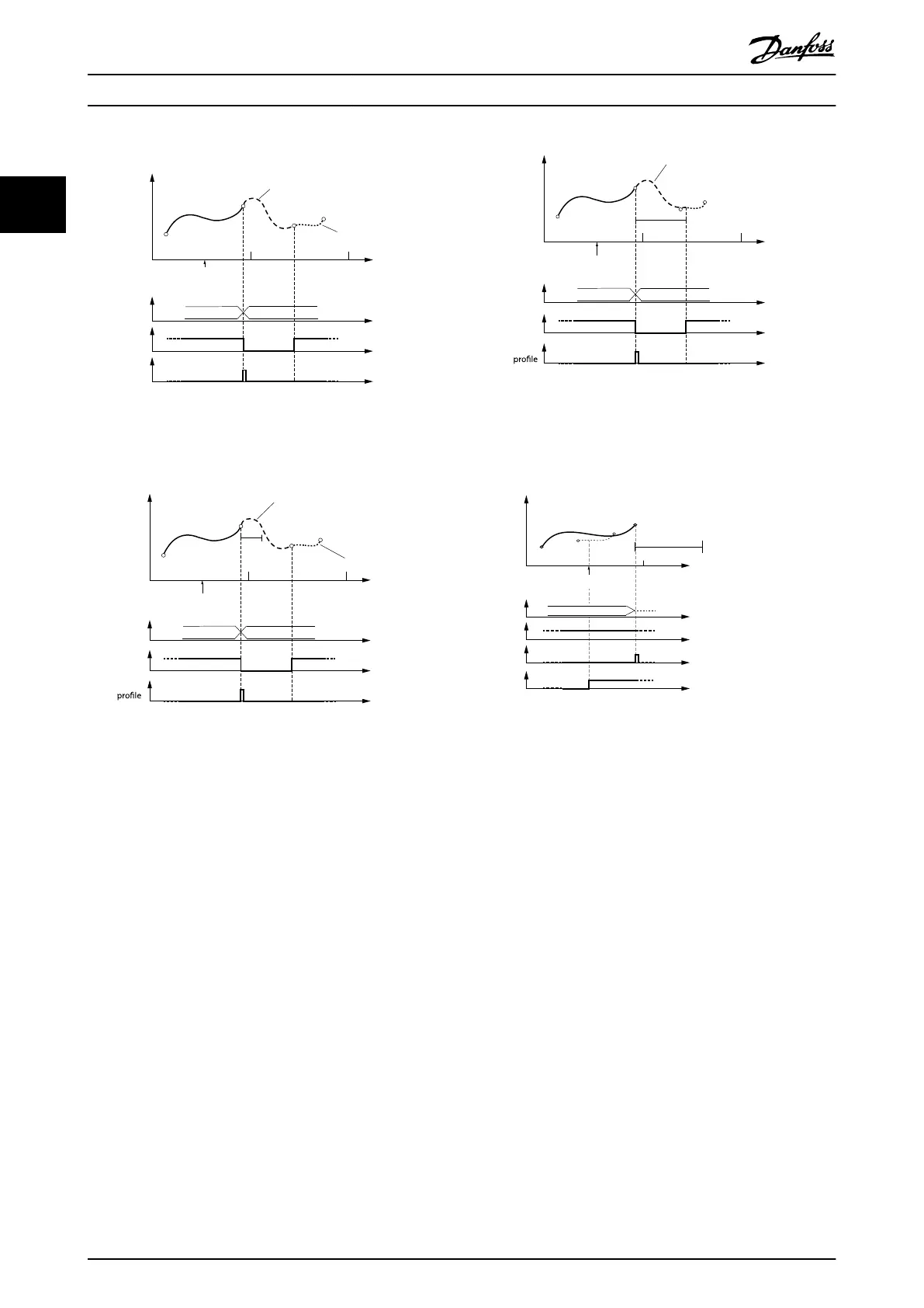
Illustration 2.49 Change CAM immediately = 0.
Do not use blending distance
Guide value
cycle
Rotor angle of axis
0 1
2
InSync
End of
Active
CAM
CAM 2 CAM 3
Blending
Master absolute
Slave absolute
Cyclic
Change CAM imm=0
Use blend dist=1
Illustration 2.50 Change CAM immediately = 0.
Use blending distance; Blending distance is not long enough
to reach the next CAM.
In Illustration 2.50, the blending distance is not long
enough to reach the 1
st
data point of the next CAM. The
axis therefore automatically increases the blending up to
the 1
st
point of the next CAM.
Guide value
cycle
Rotor angle of axis
0
1
2
InSync
End of
Active
CAM
CAM 2 CAM 3
Blending
Master absolute
Slave absolute
Cyclic
Change CAM imm=0
Use blend dist=1
130BF198.10
blend
dist
Illustration 2.51 Change CAM immediately = 0.
Use blending distance; Blending distance is long enough to
cover the gap to the next CAM.
0 1
130BF265.10
Rotor angle of axis
Master absolute
Slave absolute
Non-Cyclic
Change CAM imm=0
Use blend dist=1
InSync
End of
Prole
CAM
Error
Guide value
cycle
blend
dist
CAM 2
Active
CAM
Illustration 2.52 The end of the blend distance is not on the
new CAM in the same guide value cycle.
This situation leads to a rejection of the transition. The servo
drive acts as if the command has never been issued.
Servo Drive Operation
VLT
®
Integrated Servo Drive ISD
®
510 System
46 Danfoss A/S © 01/2017 All rights reserved. MG36D102
22

 Loading...


