Rotor angle of axis
0 1 2
Master absolute
Slave absolute
Blending
Change CAM Imm=1
Use blend dist=0
InSync
End of
Prole
Active
CAM
Guide value
cycle
CAM 2 CAM 3
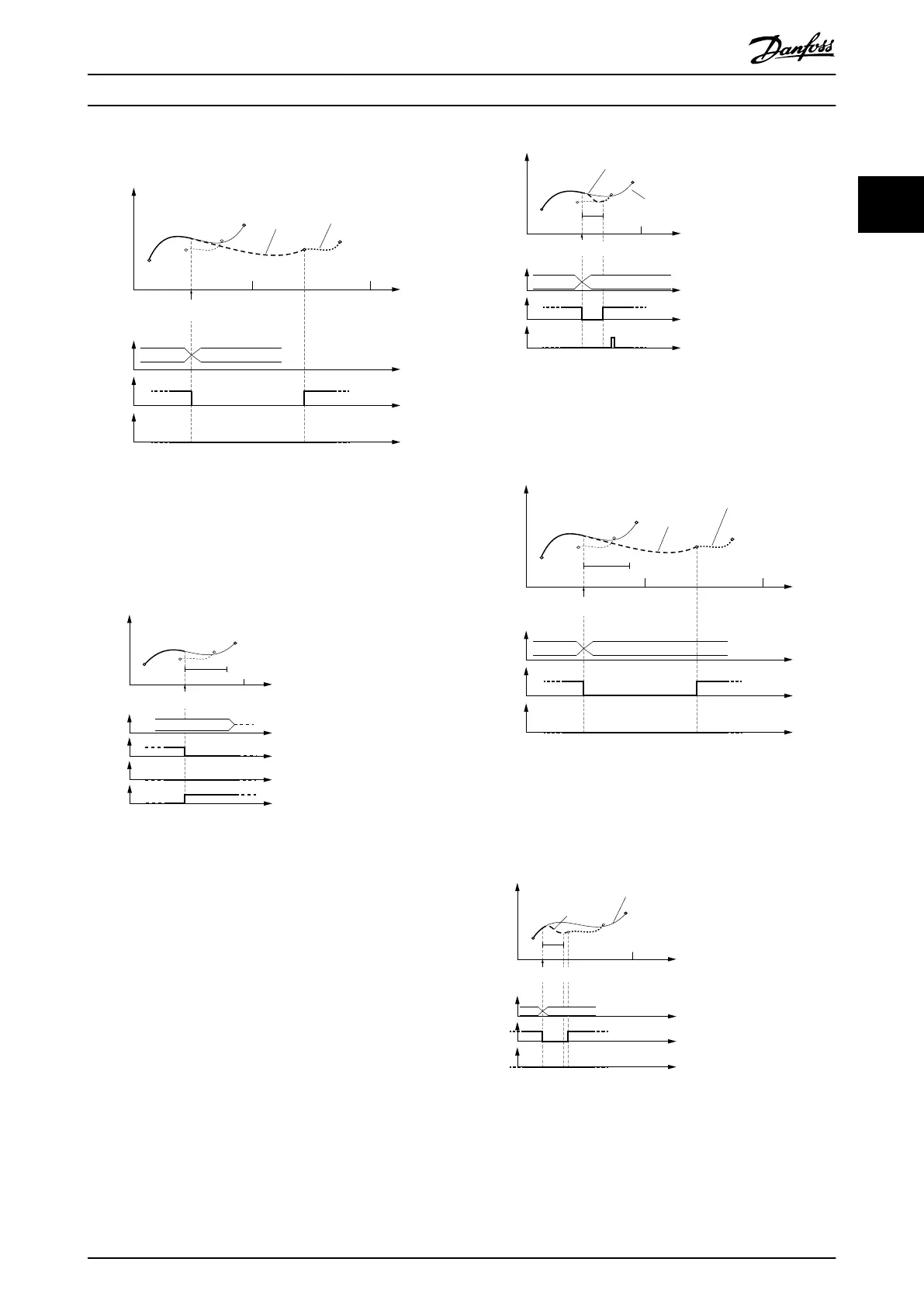
Illustration 2.53 Change CAM immediately = 1.
No blending distance used. The blending is then done
automatically to the beginning of the new CAM. It does not
necessarily mean that this is in the next cycle (for example,
see Illustration 2.57).
130BF267.10
Rotor angle of axis
10
Master absolute
Slave absolute
Non-Cyclic
blend
dist
CAM
Error
Active
CAM
InSync
End of
prole
Change CAM imm=1
Use blend dist=1
Guide value
cycle
CAM 2
Illustration 2.54 The end of the blend distance is not on the
new CAM in the same guide value cycle.
This situation leads to a reject of the transition. An error is
issued because the 1
st
CAM was aborted with Change CAM
imm = 1.
Rotor angle of axis
130BF269.10
Master absolute
Slave absolute
0 1
Active
CAM
InSync
End of
prole
Blending
blend
dist
Change CAM imm=1
Use blend dist=1
Guide value
cycle
CAM 2 CAM 3
Illustration 2.55 Change CAM immediately = 1.
Use blending distance; Blending is possible to the new CAM
prole in the same cycle.
Rotor angle of axis
0 1 2
Master absolute
Slave absolute
Cyclic
Blending
blend
dist
Active
CAM
InSync
End of
prole
Change CAM imm=1
Use blend dist=1
Guide value
cycle
CAM 2 CAM 3
Illustration 2.56 Change CAM immediately = 1.
Use blending distance; Blending distance ends after the new
CAM prole ends; Blending is then extended to the starting
point of the next cycle.
Rotor angle of axis
130BF270.10
Master absolute
Slave absolute
0 1
Blending
Active
CAM
InSync
End of
prole
blend
dist
Change CAM imm=1
Use blend dist=1
Guide value
cycle
CAM 2 CAM 3
Illustration 2.57 Use blending distance; Blending distance is
not long enough to reach the next CAM.
Servo Drive Operation Programming Guide
MG36D102 Danfoss A/S © 01/2017 All rights reserved. 47
2 2

 Loading...


