Absolute master position, relative slave position
Change CAM immediately = 0:
The currently running CAM is processed until the end. The
1
st
slave position of the new CAM is adjusted so that it
matches the slave position of the end point of the old
CAM prole.
Change CAM immediately = 1:
The currently running CAM is aborted immediately. The
slave position of the new CAM at the current guide value
is adjusted so that it matches the current slave position. If
the new CAM has not dened at this current guide value,
the slave value of the 1
st
point of the new CAM is adjusted
so that it matches the current slave position.
The behavior when switching to non-cyclic CAM
proles is
the same as detailed in section Absolute master position,
absolute slave position in chapter 2.4.5.4 Basic CAM. Options
slave absolute and slave relative have no inuence in these
cases and are therefore not mentioned again in this
section.
0 1 2
Active
CAM
InSync
End of
CAM 2 CAM 3
Slave
relative
Blending Master absolute
Slave relative
130BF272.10
Guide value
cycle
Rotor angle of axis
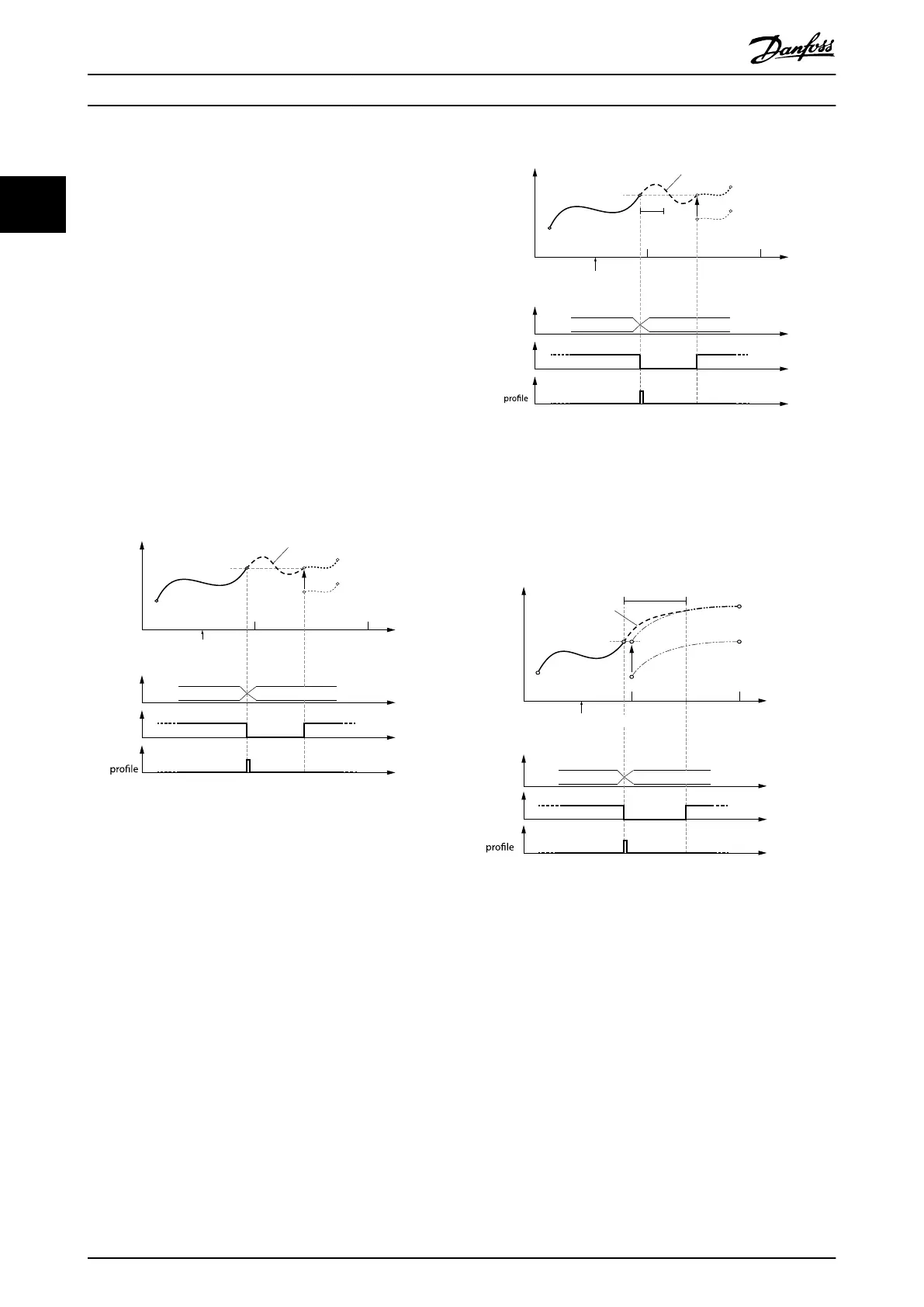
Change CAM imm=0
Use blend dist=0
Illustration 2.58 Transition with absolute master and relative
slave positioning;
No blending distance used.
0 1 2
Active
CAM
InSync
End of
CAM 2 CAM 3
Slave
relative
Blending
Master absolute
Slave relative
Cyclic
Guide value
cycle
Rotor angle of axis
blend
dist
Change CAM imm=0
Use blend dist=1
Illustration 2.59 Change CAM immediately = 0.
Use blending distance; Blending distance is not long enough
to reach the next CAM.
Guide value
cycle
Rotor angle of axis
CAM 2 CAM 1
Slave
relative
Master absolute
Slave relative
Cyclic
Blending
blend
dist
Active
CAM
InSync
End of
Change CAM imm=0
Use blend dist=1
Illustration 2.60 Change CAM immediately = 0.
Use blending distance; Blending distance is long enough to
cover the gap to the next CAM.
Servo Drive Operation
VLT
®
Integrated Servo Drive ISD
®
510 System
48 Danfoss A/S © 01/2017 All rights reserved. MG36D102
22

 Loading...


