Active
CAM
InSync
End of
prole
0 1 2
130BF274.10
Guide value
cycle
Rotor angle of axis
CAM 2 CAM 1
Master absolute
Slave relative
Slave
relative
Blending
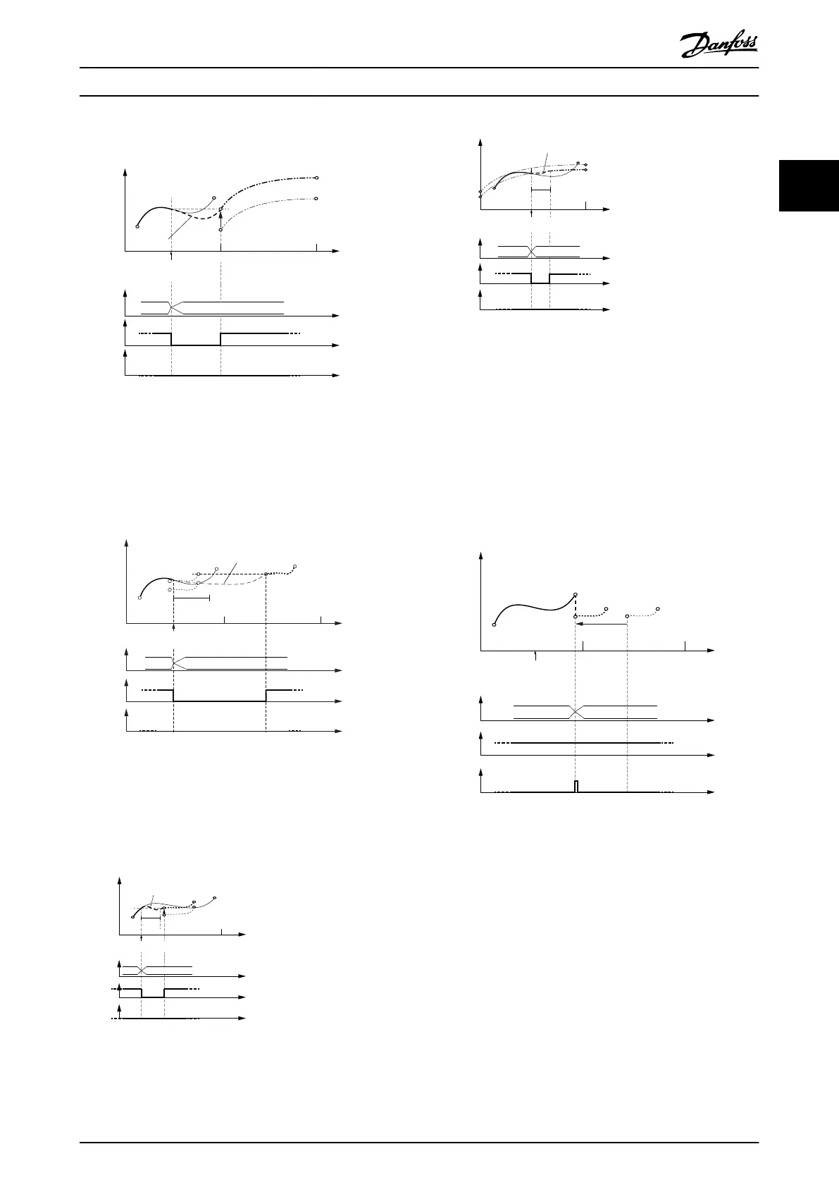
Change CAM imm=1
Use blend dist=0
Illustration 2.61 Change CAM immediately = 1.
No blending distance used. The blending is then done
automatically to the beginning of the new CAM.
It does not necessarily mean that this is in the next cycle (for
example, see Illustration 2.62).
Rotor angle of axis
Active
CAM
InSync
End of
prole
Change CAM imm=1
Use blend dist=1
CAM 2 CAM 3
Master absolute
Slave absolute
Cyclic
blend
dist
Blending
Slave
relative
Guide value
cycle
1 2
130BF572.10
Illustration 2.62 Change CAM immediately = 1.
Use blending distance; Blending distance ends after the new
CAM prole ends;
Blending is then extended to the starting point of the next
cycle.
0
1
130BF275.10
Guide value
cycle
Rotor angle of axis
Master absolute
Slave relative
Slave
relative
Blending
Active
CAM
InSync
End of
prole
blend
dist
Change CAM imm=1
Use blend dist=1
CAM 2 CAM 3
Illustration 2.63 Change CAM immediately = 1.
Use blending distance; Blending distance is not long enough
to reach the next CAM.
0 1
130BF276.10
Guide value
cycle
Rotor angle of axis
Master absolute
Slave relative
CAM 2 CAM 1
Slave
relative
Blending
Active
CAM
InSync
End of
prole
blend
dist
Change CAM imm=1
Use blend dist=1
Illustration 2.64 Change CAM immediately = 1.
Use blending distance; Blending is possible to the new prole
of the next CAM.
Relative master position, absolute slave position
In this case, the option Use blend distance is ignored. The
minimum blending distance (see chapter 7.14.11 Parameter:
Minimum Blending Distance (0x380A)) is used to calculate a
polynomial of 5
th
degree for the synchronization
movement to align the current rotor angle of the axis to
the slave position of the 1
st
data point in the CAM
prole.
Change CAM imm=0
Use blend dist=0
CAM 2 CAM 3
Guide value
cycle
Rotor angle of axis
Active
CAM
InSync
End of
prole
Master relative
Slave absolute
0 1 2
Jump in position and
velocity possible!
Master
relative
Illustration 2.65 Change CAM immediately = 0.
Do not use blending distance. If the CAMs do not match in
slave position and velocity, a jump may occur.
This would probably lead to a following error.
Servo Drive Operation Programming Guide
MG36D102 Danfoss A/S © 01/2017 All rights reserved. 49
2 2

 Loading...


