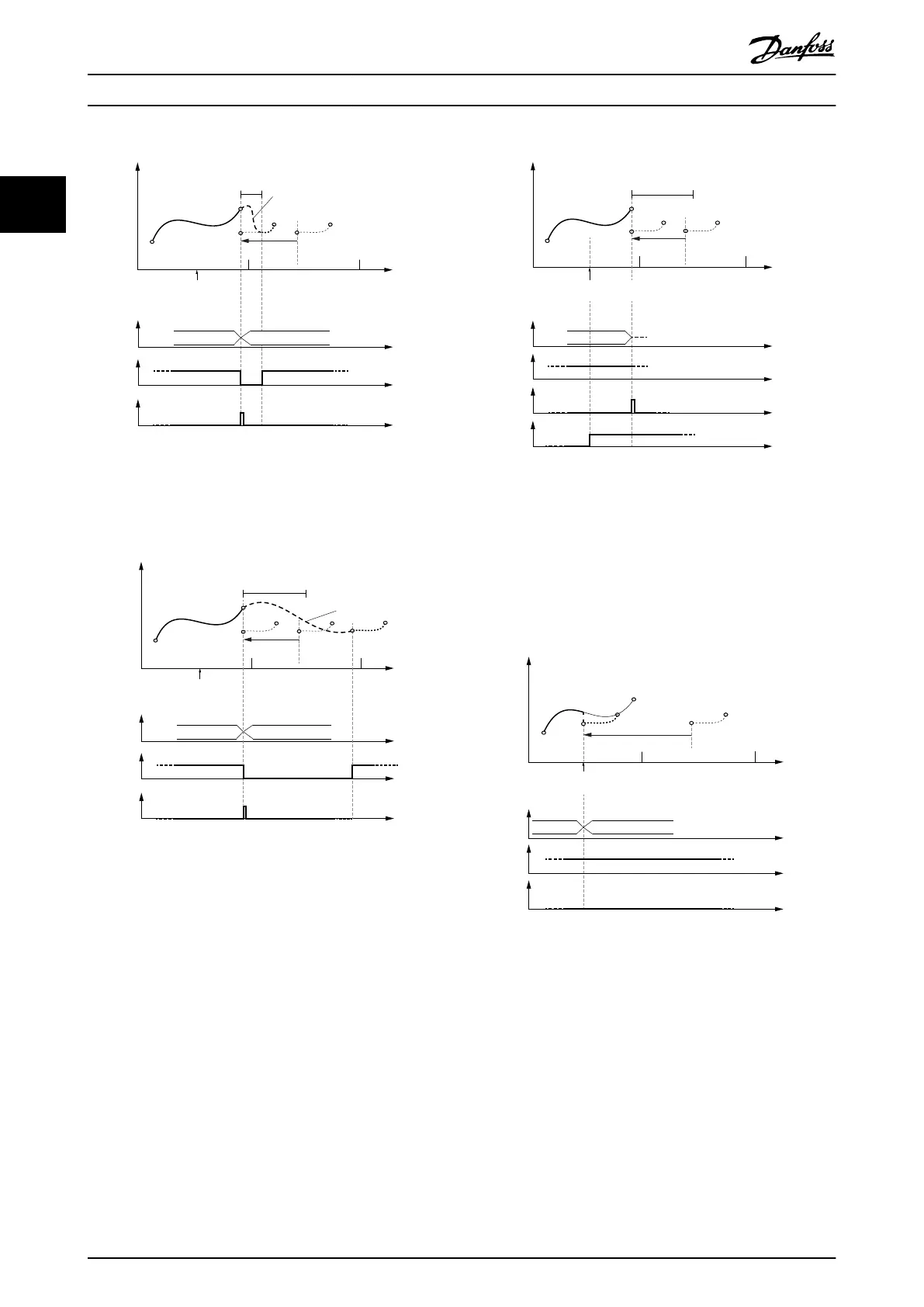
Change CAM imm=0
Use blend dist=1
CAM 2 CAM 3
130BF278.10
Guide value
cycle
Rotor angle of axis
Active
CAM
InSync
End of
prole
Master relative
Slave absolute
0 1 2
Master
relative
Blending
blend dist
Illustration 2.66 Change CAM immediately = 0.
Use blending distance; Blending distance is inside the new
CAM.
Change CAM imm=0
Use blend dist=1
CAM 2 CAM 3
130BF279.10
Guide value
cycle
Rotor angle of axis
Active
CAM
InSync
End of
prole
Master relative
Slave absolute
Cyclic
0 1 2
Master
relative
Blending
blend dist
Illustration 2.67 Change CAM immediately = 0.
Use blending distance; Blending distance ends after the end
point of the new CAM.
Change CAM imm=0
Use blend dist=1
Master relative
Slave absolute
Non- cyclic
blend
dist
Guide value
cycle
Rotor angle of axis
0
1 2
Master
relative
Active
CAM
InSync
End of
prole
CAM
Error
CAM 2
Illustration 2.68 The end of the blend distance is not on the
new CAM.
This situation leads to rejection of the transition. An error is
issued
because the 1
st
CAM was aborted with Change CAM
immediately = 1.
Guide value
cycle
Rotor angle of axis
0
1
2
Active
CAM
InSync
End of
prole
Master relative
Change CAM imm=1
Use blend dist=0
Master relative
Slave absolute
Jump in position and
velocity possible!
CAM 2 CAM 3
Illustration 2.69 Change CAM immediately = 1.
No blending distance used. If the CAMs do not match in slave
position and velocity, a jump may occur.
This may lead to a following error.
Servo Drive Operation
VLT
®
Integrated Servo Drive ISD
®
510 System
50 Danfoss A/S © 01/2017 All rights reserved. MG36D102
22

 Loading...


