Guide value
cycle
Rotor angle of axis
0
1
2
Master relative
Slave absolute
Cyclic
Active
CAM
InSync
End of
prole
Change CAM imm=1
Use blend dist=1
Master
relative
blend
dist
Blending
CAM 2 CAM 3
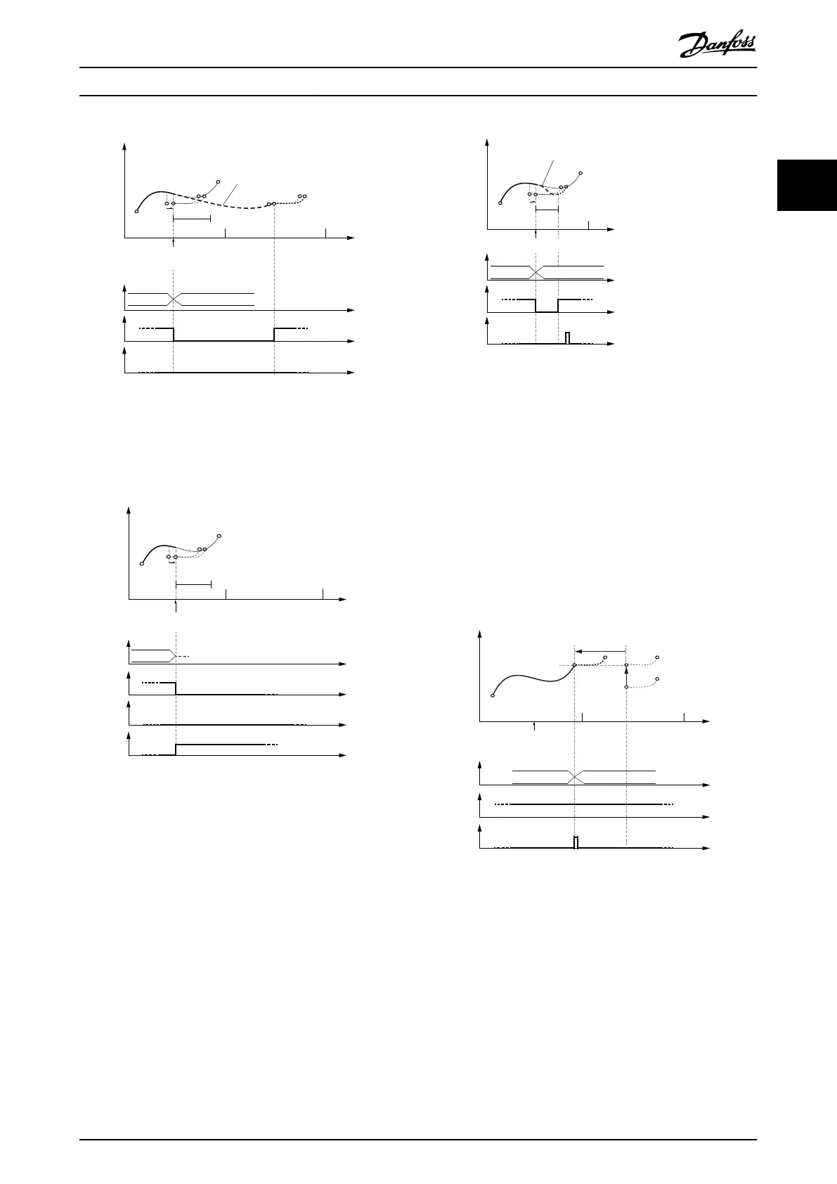
Illustration 2.70 Change CAM immediately = 1.
Use blending distance; Blending distance ends after the end
point of the new CAM.
Guide value
cycle
Rotor angle of axis
0
1 2
Master relative
Slave absolute
Non- cyclic
blend
dist
Master
relative
Change CAM imm=1
Use blend dist=1
Active
CAM
InSync
End of
prole
CAM
Error
CAM 2
Illustration 2.71 The end of the blend distance is not on the
new CAM.
The transition is rejected and the servo drive acts as if the
command was never issued.
130BF284.10
Master relative
Slave absolute
blend distMaster
relative
Guide value
cycle
Rotor angle of axis
0
1
Change CAM imm=1
Use blend dist=1
Active
CAM
InSync
End of
prole
Blending
CAM 2 CAM 3
Illustration 2.72 Change CAM immediately = 1.
Use blending distance; Blending distance is shorter than the
new CAM prole.
Relative master position, relative slave position
The processing starts as soon as the CAM prole is
activated. The 1
st
point of the CAM prole is moved to the
current position and guide value. The behavior when
switching to non-cyclic CAM proles is the same as shown
in section Relative master position, absolute slave position in
chapter 2.4.5.4 Basic CAM. Option slave absolute or slave
relative has no inuence in these cases and is therefore not
mentioned again in this chapter.
Guide value
cycle
Rotor angle of axis
0
1
2
CAM 2 CAM 3
Active
CAM
InSync
End of
prole
Change CAM imm=0
Use blend dist=0
Master relative
Slave relative
Master relative
Jump in
velocity possible!
Slave
relative
Illustration 2.73 CAM prole with relative master and relative
slave positioning.
A jump in velocity may occur if the CAMs do not match.
Servo Drive Operation Programming Guide
MG36D102 Danfoss A/S © 01/2017 All rights reserved. 51
2 2

 Loading...


