Guide value
cycle
Rotor angle of axis
0
1
2
CAM 2 CAM 3
Active
CAM
InSync
End of
Change CAM imm=0
Use blend dist=1
Master relative
Slave relative
Master relative
Slave
relative
Blending
blend dist
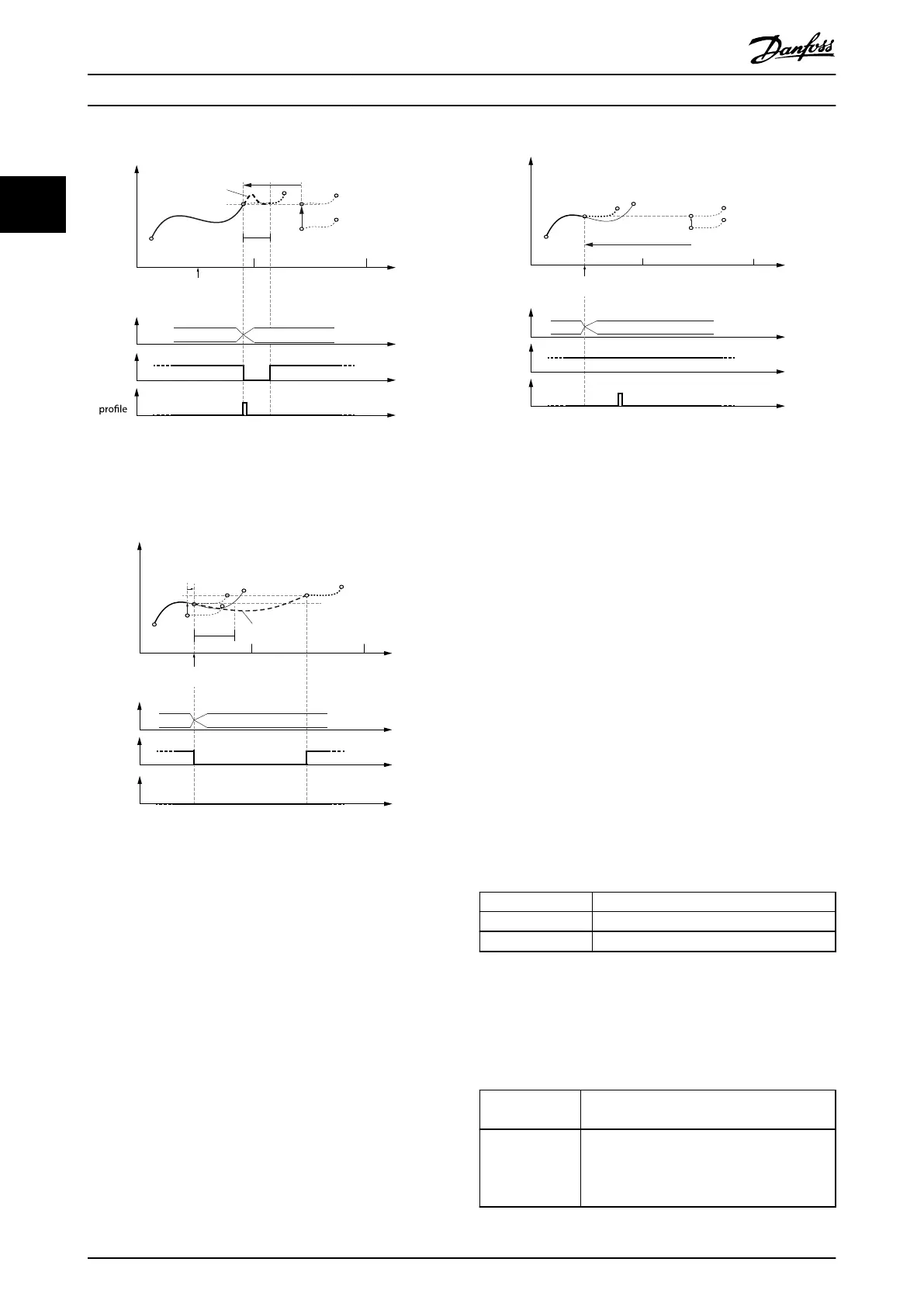
Illustration 2.74 Change CAM immediately = 0.
Use blending distance.
Guide value
cycle
Rotor angle of axis
0
1
2
Active
CAM
InSync
End of
prole
CAM 2 CAM 3
Change CAM imm=1
Use blend dist=1
Master relative
Slave relative
Cyclic
Slave
relative
Master
relative
Blending
blend
dist
Illustration 2.75 Change CAM immediately = 1.
Use blending distance; Distance is longer than the new CAM.
130BF288.10
Guide value
cycle
Rotor angle of axis
0
1
2
CAM 2 CAM 3
Active
CAM
InSync
End of
prole
Change CAM imm=1
Use blend dist=0
Master relative
Jump in
velocity possible!
Slave
relative
Master relative
Slave relative
Illustration 2.76 Change CAM immediately = 1.
Do not use blending distance. Jumps in velocity may occur.
2.4.5.5 Advanced CAM
The advanced CAM is represented by nodes and segments.
The available node types are described in Table 2.13. The
available segment types are described in Table 2.14.
The CAM conguration options Slave absolute and Slave
relative are not available for advanced CAM. In advanced
CAM, the behavior of an absolute or relative movement is
built in to the dierent segment types.
A dierentiation between full and partial CAM is not
applicable for advanced CAM. An advanced CAM can
contain paths that form a circle, and alternative paths (see
Illustration 2.78), which end at nodes without further
following segment.
An advanced CAM prole can consist of several nodes,
segments, actions, and exit conditions. The size of a CAM
prole highly depends on the number of elements and, for
example, on the segment types (some require more and
others require fewer parameters).
Name Description
GuideNode Connects GuideSegments
EventNode Connects EventSegments
Table 2.13 Available Node Types
All nodes are non-signaling nodes. The axis does not
automatically signal if it passes a node. However, for
example for debugging purposes, it is possible to enable
this signaling for selected nodes.
GuidePoly GuideSegment
Polynomial of 5
th
order based on guide value.
MoveDistance-
Segment
GuideSegment
Uses run-time calculated polynomial of 5
th
order; the angle is sent over eldbus at run-
time.
Servo Drive Operation
VLT
®
Integrated Servo Drive ISD
®
510 System
52 Danfoss A/S © 01/2017 All rights reserved. MG36D102
22

 Loading...


