FlyingStop-
Segment
GuideSegment
Constant speed, followed by braking ramp,
angle of constant movement is sent over
eldbus at run-time.
ReturnSegment GuideSegment
Turns shaft to a symmetric angle (absolute
position) to eliminate rounding errors.
EventSegment-
Container
GuideSegment
All time-related movements must be
encapsulated by this segment type.
TimePoly EventSegment
Polynomial of 5
th
order based on time.
VelocitySegment EventSegment
Constant velocity, independent of the guide
value.
SyncSegment EventSegment
Constant velocity, depending on the guide
value.
TorqueSegment EventSegment
Constant torque, independent of the guide
value.
PwmOSegment EventSegment
Turns o the PWM.
FrictionSegment EventSegment
Determines the friction of the system.
Table 2.14 Available Segment Types
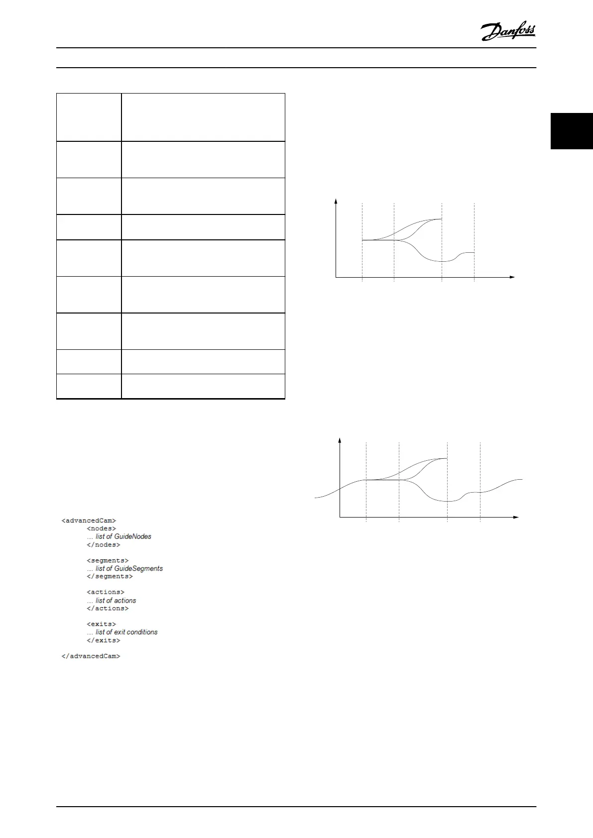
This CAM
prole type can only be used with forward
turning guide values.
The advanced CAM prole consists of a list of nodes
(containing GuideNodes), a list of segments (containing
GuideSegments), an optional list of actions, and an optional
list of exit conditions.
Illustration 2.77 Advanced CAM Prole
Nodes
Nodes are dened by their position on the guide value.
The slave position is dened, where necessary, inside the
segments. The starting node of a CAM is the node with
nodeID 0. In a CAM, there must be exactly 1 starting node
(1 node with ID 0). However, this starting node does not
need to be the 1
st
node of the CAM (see Illustration 2.78).
The starting node must be a guide node.
End nodes dene the end of a non-cyclic CAM, or the end
when switching non-immediate to another CAM. Only
guide nodes can be end nodes. A guide node that has no
following segment is automatically dened as an end
node.
130BF289.10
Guide
value
nodeID
3
nodeID
0
nodeID
1
nodeID
2
segID 1
segID 2
segID 3
segID 4
segID 5
Rotor angle
of axis
Illustration 2.78 NodeID 2 has no following segment:
It automatically becomes an end node.
An advanced CAM must have at least 1 end node, however
it is possible to have >1 end node within a CAM. If no end
node is explicitly dened, and there is no node without a
following segment (that implicitly would be an end node),
the start node becomes an end node.
130BF290.10
Guide
value
Rotor angle
of axis
nodeID
3
nodeID
0
nodeID
1
nodeID
2
segID 1
segID 2
segID 3
segID 4
segID 5
segID 6
segID 6
Illustration 2.79 No end node explicitly dened and no node
without following segment dened in the CAM.
NodeID 0 (start node) automatically becomes the end node.
A non-cyclic CAM ends at the 1
st
end point that is
processed. This can take several cycles of guide value or
continue innitely if there is no end node within the
currently processed path. For example, in Illustration 2.79,
when the path is set in a way that segID 1 is used instead
of segID 2, the start node is not in the active path.
A cyclic CAM just passes an end node like every normal
node; the End of Prole bit (see chapter 7.14.8 Parameter:
CAM Prole Status (0x3805)) is set. This bit is set for every
end node that is passed within a cyclic CAM. So, the end
of prole bit can also be set several times within 1 cycle. It
is also possible that it is not set at all if there is no end
node within the processed path.
Servo Drive Operation Programming Guide
MG36D102 Danfoss A/S © 01/2017 All rights reserved. 53
2 2

 Loading...


