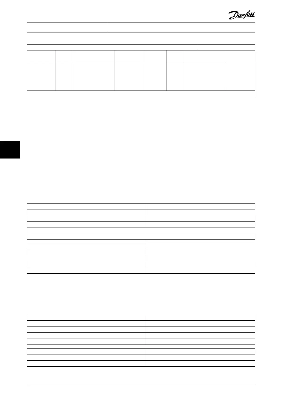
15 14 13 12 11 10 9 8 7 6 5 4 3 2 1 0
Polarity input 2 Reserved Debounce count Function input 2
Polarity
input 1
Reserved Debounce count Function input 1
1: Invert – Default: 0 (no debounce)
0: Analog 2
1: Digital 2
2: Left limit
3: Right limit
4: Home
1: invert – Default: 0 (no debounce)
0: Analog 1
1: Digital 1
2: Left limit
3: Right limit
4: Home
MSB LSB
Table 7.230 0x200F: Input Conguration Denition
If both inputs are congured as Left limit or both inputs are congured as Right limit, the logical disjunction (OR) of the
input values is evaluated for the limit switches.
If both inputs are
congured as Home, the logical disjunction (OR) of the input values is evaluated for the home switch.
Other input conicts are rejected.
The term Left limit denotes the negative limit switch, and the term Right limit denotes the positive limit switch.
The limit and home switch input must be congured using the polarity bit so that the logical state is high when the limit
switch is active (limit is reached).
If an input is congured as digital, it can be used as a touch probe input. It is debounced by using a dened number of
samples taken at the cycle time of the PWM frequency. The value of the analog input is given as a physical value.
Attribute Value
Index 0x200F
LCP parameter number –
Name Dual analog user inputs cong
Object code Var
Data type UNSIGNED16
Sub-index 0x00
Access Read/write
PDO mapping No
Value range See Table 7.230.
Default value 0
Table 7.231 0x200F: Dual Analog User Inputs Cong
7.21.4 Parameter 16-66: Digital Outputs (0x60FE)
This object commands simple digital outputs. It represents the physical output levels.
Attribute Value
Index 0x60FE
Name Digital outputs
Object code Array
Data type UNSIGNED32
Sub-index 0x00
Description Value of highest sub-index
Access Const
Servo Drive Parameter Descr...
VLT
®
Integrated Servo Drive ISD
®
510 System
338 Danfoss A/S © 01/2017 All rights reserved. MG36D102
77

 Loading...


