2.4.5.4 Basic CAM
Data points
The basic CAM consists of data points, which all have the same structure. There can be a maximum of 256 or 1024 data
points inside 1 basic CAM (see chapter 7.14.1 Parameter: CAM Prole Memory Layout (0x380F)).
Illustration 2.39 Basic CAM Data Points
Attribute
Mandatory/optional (+default
value)
Value range/allowed
values
Description
masterPos M Float: [0;1] Master position for this data point. Given in revolutions of
guide value. The masterPos inside a CAM prole is always
dened from 0 to 1.
slavePos M Float Axis position for this data point. Given in revolutions of rotor
position. SlavePos describes the position on the motor side.
vel O;
default = 0
Float Velocity of the axis in this data point. The velocity must be
given as a factor between the velocity of the axis in relation to
the velocity of the guide value (1 revolution of the axis per 1
round of guide value). Jumps in velocity are not possible.
acc O;
default = 0
Float Acceleration of the axis in this data point. The acceleration
must be given as a factor between the acceleration of the axis
in relation to the velocity of the guide value (1 revolution of
axis per square of round of guide value). Jumps in acceleration
are not possible.
Table 2.12 Attributes for a Data Point
All data points are non-signaling data points. The axis does
not automatically signal if it passes a data point. However,
it is possible to enable this signaling for selected data
points, for example for debugging purposes.
CAM conguration: Slave absolute/relative
When using the slave absolute option for a basic CAM, the
values of the slavePos attribute in the data point are used.
When using the slave relative option, the start of the CAM
is transferred to the current position of the slave.
CAM conguration: cyclic/non-cyclic
The dierent congurations are explained using
illustrations. There are 3 basic CAMs dened to show all
situations:
•
Illustration 2.40 shows a full CAM (1
st
data point
at masterPos 0, last data point at masterPos 1),
which has a velocity unequal to 0 in the 1
st
data
point.
•
Illustration 2.41 and Illustration 2.42 show partial
CAMs (1
st
data point not at masterPos 0, last data
point not at masterPos 1).
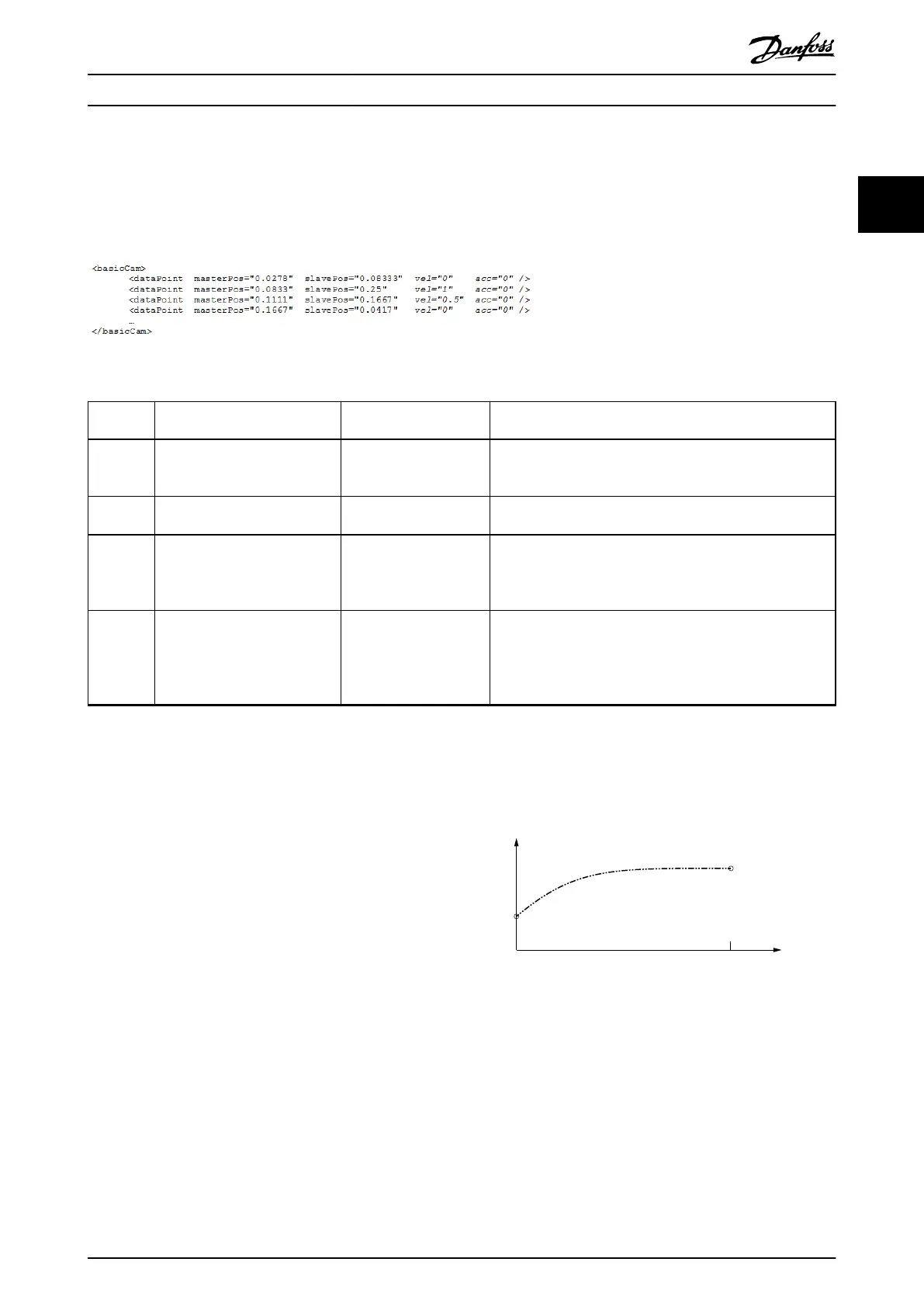
In the following chapters, several situations are dened.
The mentioned CAMs are used throughout the description
of the basic CAM to cover all situations.
Illustration 2.40 CAM 1 - Full CAM with Velocity of Last Node/
point = 0
Servo Drive Operation Programming Guide
MG36D102 Danfoss A/S © 01/2017 All rights reserved. 43
2 2

 Loading...


