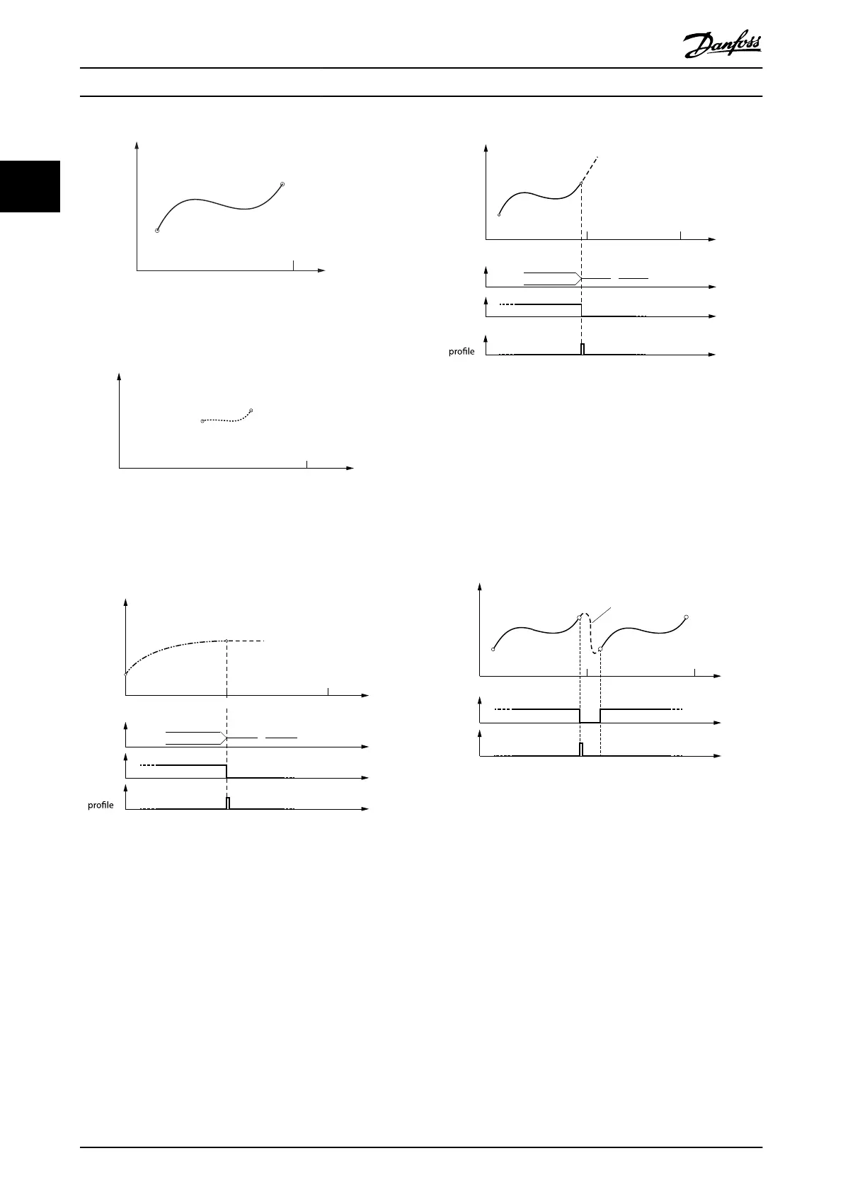
Illustration 2.41 CAM 2 - Partial CAM
Guide value
Rotor angle of axis
0 1
Illustration 2.42 CAM 3 - Partial CAM
Non-cyclic CAM execution
Rotor angle of axis
0 1 Guide value
cycle
2
Non-cyclic
CAM 1
Active
CAM
InSync
End of
0
130BF190.10
Illustration 2.43 CAM 1: Full CAM - Non-cyclic: Velocity at the
End is 0
0 1 2
Non-cyclic
CAM 2
Active
CAM
InSync
End of
0
130BF191.10
Rotor angle of axis
Guide value
cycle
Illustration 2.44 CAM 2: Partial CAM - Non-cyclic: Velocity at
the End is Unequal to 0
If the last data point of a CAM prole has a velocity other
than 0, and ends in this data point (for example, because
of non-cyclic conguration), the axis keeps on turning at
the velocity of this last data point (see Illustration 2.44).
However, the velocity is still related to the guide value. The
acceleration of this last data point is automatically set to 0.
Cyclic CAM execution
InSync
End of
prole
Rotor angle of axis
0 1
Guide value
cycle
2
Slave absolute
Cyclic
Blending
130BF192.10
Illustration 2.45 CAM 2: Partial CAM - Cyclic: Blending
Segment is an Automatically Calculated P5
Servo Drive Operation
VLT
®
Integrated Servo Drive ISD
®
510 System
44 Danfoss A/S © 01/2017 All rights reserved. MG36D102
22

 Loading...


