InSync
End of
prole
Rotor angle of axis
0 1
Guide value
cycle
2
Slave relative
Cyclic
Blending
130BF193.10
Slave
relative
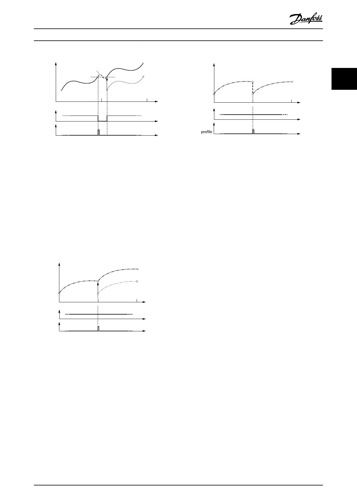
Illustration 2.46 CAM 2: Partial CAM - Cyclic, Slave relative:
Blending Segment is an Automatically Calculated P5.
The CAM is adjusted in a way that the 1
st
rotor angle value
matches the rotor angle of the last node.
A special case in Illustration 2.46 is when the velocity of the
last point and the velocity of the 1
st
point are both 0. Then
the P5 is actually a P0.
For smooth movements with cyclic use of fully dened
CAM proles, the 1
st
and the last data point of the proles
must match each other. “Matching” means having the
same velocity value and, depending on the conguration,
also the slave position value (see Illustration 2.47 and
Illustration 2.48).
Rotor angle of axis
0 1
Guide value
cycle
2
Slave relative
Cyclic
Slave
relative
InSync
End of
prole
Jump in velocity!
130BF194.10
Illustration 2.47 Cyclic, Full CAM Prole Dened Over the
Whole Guide Value Cycle.
The velocity of the 1
st
and the last node are not equal. During
execution, a jump may occur.
Rotor angle of axis
0 1
Guide value
cycle
2
Slave absolute
Cyclic
InSync
End of
Jump in position
and velocity!
130BF195.10
Illustration 2.48 Cyclic, Full CAM Prole.
The velocity and the position of 1
st
and last nodes do not
match.
Switching between CAM proles
Depending on the CAM conguration options Master
absolute/relative and Slave absolute/relative, there are
several methods to transition from 1 running CAM prole
to the next. All the possibilities are described in the
illustrations in this section. The examples all show the
starting point based on the time of the CAM activation
request, or when CAM ack (bit 12) is set by the axis (see
chapter 2.4.5.1 Activating a CAM prole).
All illustrations in the following sub-chapters show the
transition from currently running CAM 2 (see
Illustration 2.41) to a newly activated CAM 1 (see
Illustration 2.40) or CAM 3 (see Illustration 2.42). The CAM
itself is always the same, but the illustrations show the
behavior with dierent congurations and settings.
The following conventions are used for transitions between
proles:
•
The blending distance has no inuence on the
position of the CAM (for example, regarding the
automatically calculated relative oset).
•
If a CAM prole is aborted (Change CAM
imm = 1), the current slave position is considered
as end slave position.
•
When activating a non-cyclic CAM prole with
Use blend distance = 0, the processing takes place
in the same master cycle (as the CAM activation
request) or in the next one (depending on the
end point of the currently running CAM prole
and the start point of the new CAM prole). In
both cases, the prole is processed as 1 complete
cycle (starting with the next upcoming start
node).
•
When activating a non-cyclic CAM prole with
Use blend distance = 1, the processing of it (at
least the start point) takes place in the same
master cycle (as the CAM activation request),
otherwise a CAM error is issued.
Servo Drive Operation Programming Guide
MG36D102 Danfoss A/S © 01/2017 All rights reserved. 45
2 2

 Loading...


