Workow to parameterize a trace
1. Write the IDs of the signals to trace into object
0x5001, sub-indexes 1 to N. Use the channels in
ascending order without gaps.
2. Use the signal tracer control object (0x5000) to
congure the trace settings:
- Number of used channels
- Task level
- Trigger slop and mode
- Number of samples to record
- Subsampling
- Amount of pre-trigger history
- ID of the Trigger signal
- Trigger level
3. Start the trace by writing to object 0x5000, sub-
index 2.
4. Poll object 0x5000, sub-index 1 for the
appearance of the data ready ag.
5. Upload the trace data from object 0x5002.
6. Separate the samples into the dierent channels.
2.7.3 Following Error Detection
A following error is signaled in all position controlled
modes of operation (see chapter 7.5.1 Parameter 52-00:
Modes of Operation (0x6060)). A position actual value (see
chapter 7.7.5 Parameter 50-03: Position Actual Value (0x6064))
outside the allowed range of the following error window
(see chapter 7.22.1.1 Parameter: Following Error Window
(0x6065)) around a position demand value (see
chapter 7.7.1 Parameter: Position Demand Value (0x6062)) for
longer than the following error timeout (see
chapter 7.22.1.2 Parameter: Following Error Time Out
(0x6066)) results in setting bit 13: Following error in the
Statusword to 1. This window for the accepted following
error tolerance is dened symmetrically around the
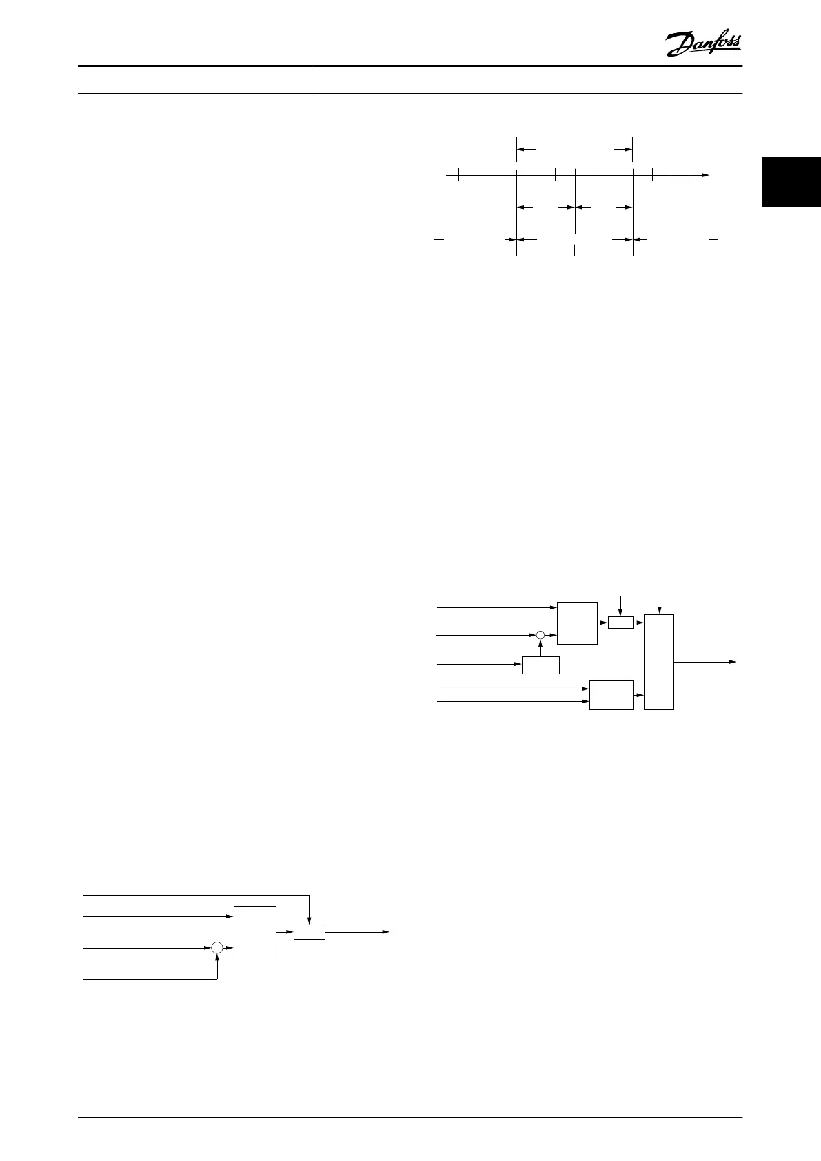
reference position (see Illustration 2.134).
Following error
Following error time out (0x6066)
Following error window (0x6065)
Position demand value
Position actual value (0x6064)
(0x6062)
Illustration 2.133 Following Error - Functional Description
130BF230.10
Accepted following
error tolerance
Following
error
window
Following
error
window
No following error
Position
Following errorFollowing error
Reference
position
Illustration 2.134 Following Error Window
The behavior of the servo drive when a following error
occurs, can be inuenced by using the Following error
option code (see chapter 7.20.3 Parameter 50-43: Following
Error Option Code (0x2055)).
2.7.4 Standstill Detection
The standstill reached function oers the possibility to
dene a velocity range around velocity 0 to be regarded as
standstill. If the velocity of a servo drive is within this area
for a specied time (velocity window time), the servo drive
is regarded to be in standstill.
Target reached option code (0x2054)
Velocity threshold time (0x6070)
Velocity threshold (0x606F)
Velocity actual value
0
0
Velocity demand value (0x606B)
Timer
Selector
Comparator
Window
comparator
Limit
function
Standstill reached
–
(0x606C)
Illustration 2.135 Standstill Reached - Functional Description
Illustration 2.136 shows the denitions for the sub-function
Standstill reached (see chapter 7.22.2 Standstill Detection
Objects). A window is dened for the accepted velocity
range symmetrically around 0 velocity. If a servo drive is
running within the accepted standstill range over the
Velocity threshold time (see chapter 7.22.2.2 Parameter:
Velocity Threshold Time (0x6070)), the servo drive is
regarded to be in standstill.
Servo Drive Operation Programming Guide
MG36D102 Danfoss A/S © 01/2017 All rights reserved. 87
2 2

 Loading...


