130BF199.10
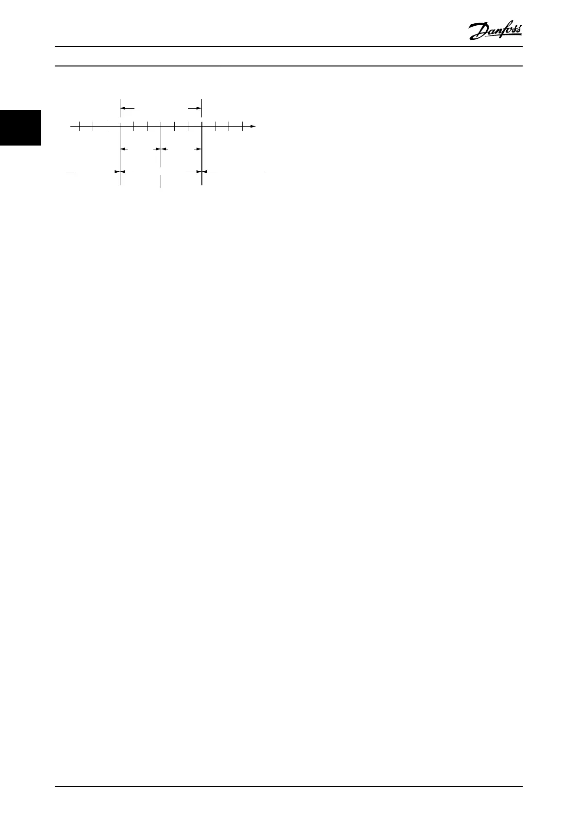
Accepted standstil
range
Velocity
Velocity
threshold
Velocity
threshold
Standstill reached
Standstill not
reached
Standstill not
reached
0
Illustration 2.136 Standstill Reached Window
2.7.5 Constant Velocity Detection
The constant velocity detection function oers the
possibility to dene a symmetrical range of accepted
velocity changes (see chapter 7.22.3.1 Parameter 51-70:
Constant Velocity Window (0x2030)), relative to the last
velocity. If the velocity of a servo drive is within this area
for a specied time, the constant velocity window time
(see chapter 7.22.3.2 Parameter 51-71: Constant Velocity
Window Time (0x2031)), the servo drive is regarded to be
running at constant velocity.
The working principle is the same as for standstill
detection (see chapter 2.7.4 Standstill Detection).
2.7.6 STO and Brake Status
The voltage is checked against a dened threshold (by the
hardware) and the state is made available to the
application for utilization with the DS402 state machine.
The safety functionality itself is not part of the software.
The STO (Safe Torque O) voltage state inuences the
DS402 state machine. The servo drive cannot be operated
if the STO voltage is not active.
If the servo drive receives the command to enter DS402
state Operation enabled, it checks if the STO voltage is
present or not. If it is not present, the servo drive enters
state Fault and signals the occurrence of an error as
described in chapter 2.7.1 Errors and Warnings.
If the servo drive is already in DS402 state Operation
enabled, it continuously monitors whether the STO voltage
is present or not. If it is not present, the servo drive enters
state Fault and signals the occurrence of an error as
described in chapter 2.7.1 Errors and Warnings.
The error code used for these 2 situations is the same and
is detailed in chapter 9.2.1 Troubleshooting. STO information
is available in objects 0x6041 (see chapter 7.3.1 Parameter
16-03 Statusword (0x6041)) and 0x2007 (see
chapter 7.22.8 Parameter 50-09: STO Voltage and Brake Status
(0x2007)).
Servo Drive Operation
VLT
®
Integrated Servo Drive ISD
®
510 System
88 Danfoss A/S © 01/2017 All rights reserved. MG36D102
22

 Loading...


