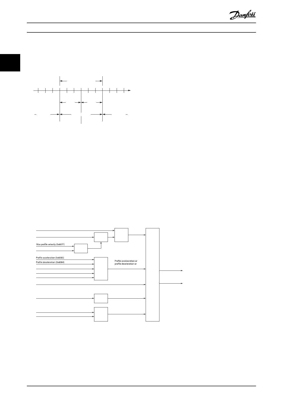
Illustration 2.18 shows the denition of the sub-function position reached. A window is dened for the accepted position
range symmetrically around the target position. If a servo drive is situated in the accepted position range over the time
position window time, the bit Target reached (bit 10) in the Statusword is set to 1.
Accepted position range
Position
window
Position not
reached
Position not
reached
Position reached
Target
position
Position
Position
window
130BF174.10
Illustration 2.18 Position Reached Window
2.4.2 Prole Velocity Mode
In Prole velocity mode, the servo drive is operated under velocity control and executes a movement with a dened velocity
(see chapter 7.11.1 Parameter 52-20: Target Velocity (0x60FF)). Parameters such as acceleration (see chapter 7.5.7 Parameter
50-11: Prole Acceleration (0x6083)) and deceleration (see chapter 7.5.8 Parameter 50-12: Prole Deceleration (0x6084)) can be
parameterized. Parameters that inuence the Prole velocity mode can be found in Illustration 2.19.
This functionality can be commanded using function block MC_MoveVelocity_ISD51X (see chapter 6.5.5.7 MC_MoveVe-
locity_ISD51x). This functionality can also be used via the LCP (see the Velocity mode section in chapter 4.3.5.1 Servo Drive). In
Prole velocity mode, the velocity control loop is used to reach the target velocity (see chapter 7.11.1 Parameter 52-20: Target
Velocity (0x60FF)).
Drive mirror mode (0x2016,02)
Target velocity (0x60FF) Limit
function
Limit
function
Trajectory
generator
d/dt
Minimum
comparator
Minimum
comparator
Multiplier
Max motor speed (0x6080)
Position actual value (0x6064)
Max torque (0x6072)
Torque limit
Feed forward
torque
Velocity demand
value (0x6068)
Velocity limit
quick-stop deceleration
Application torque limit (0x2053)
Max acceleration (0x60C5)
Max deceleration (0x60C6)
Quick-stop deceleration (0x6085)
Quick-stop option code (0x605A)
Illustration 2.19 Prole Velocity Mode Control Function
The usage of acceleration and deceleration for the calculation of the trajectory is shown in Illustration 2.20.
Servo Drive Operation
VLT
®
Integrated Servo Drive ISD
®
510 System
30 Danfoss A/S © 01/2017 All rights reserved. MG36D102
22

 Loading...


