The PLC library provides the information in function block
chapter 6.5.6.9 DD_ReadCamInfo_ISD51x.
2.4.6 Gear Mode
In Gear mode, the servo drive executes a synchronized
movement based on a master axis by using a gear ratio
between the master and the slave position. The guide
value can be provided by an external encoder, virtual axis,
or the position of another axis. This functionality can be
commanded using function block MC_GearIn_ISD51x (see
chapter 6.5.5.9 MC_GearIn_ISD51x) and
MC_GearInPos_ISD51x (see
chapter 6.5.5.10 MC_GearInPos_ISD51x).
The slave axis calculates its position out of the master
position value (see chapter 7.8.1 Parameter: Position Guide
Value (0x2060)). The slave axis sets its target position
corresponding to the congured gear ratio (see
chapter 7.15.1 Parameter: Gear Ratio (0x3900)). The principle
of the Gear mode is shown in Illustration 2.114.
Master axis
Master position
Slave
position
Slave drive
Slave axis
Gear acceleration
Gear deceleration
Gear ratio numerator
Gear denominator
130BF573.10
Illustration 2.114 Gear Mode Description
The slave velocity is calculated as:
x master velocitySlave velocity =
gear ratio numerator
gear ratio denominrator
To start a geared movement, the acceleration (see
chapter 7.5.7 Parameter 50-11: Prole Acceleration (0x6083))
and deceleration (see chapter 7.5.8 Parameter 50-12: Prole
Deceleration (0x6084)) can also be congured. These
parameters are also used to link up the gear. The slave
ramps up or down to the ratio of the master velocity
according to the given acceleration or deceleration value
and locks in when this velocity is reached.
There are 2 synchronization methods:
•
The relative synchronization between the master
and the slave is important (Gear In functionality).
For the Gear In functionality, the synchronization
phase is velocity controlled, so any lost distance
during synchronization is not caught up.
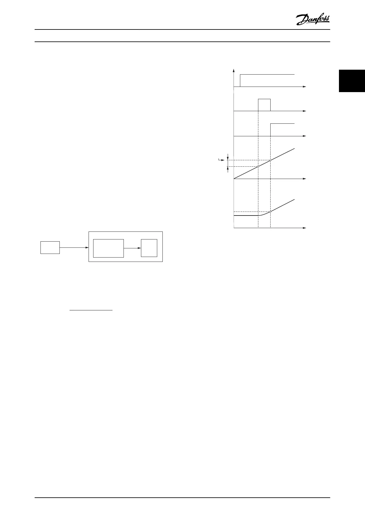
•
The absolute relation between master and slave is
important (Gear In Pos functionality), as shown in
Illustration 2.115.
t
t
t
t
t
TRUE
FALSE
Master sync position
Master start distance
Slave sync position
Execute
Start sync
Insync
130BF574.10
TRUE
TRUE
FALSE
FALSE
FALSE
Illustration 2.115 Timing Diagram for Gear In Position
Procedure
A polynomial of maximum 5
th
degree is used for the
synchronization phase.
The mode is activated by writing –7 to object 0x6060.
For the Controlword (see chapter 7.2.1 Parameter 16-00
Controlword (0x6040)) and the Statusword (see
chapter 7.3.1 Parameter 16-03 Statusword (0x6041)), the bits
that usually hold the operating mode-specic bits are
dened here.
Depending on the value of the Guide value option code
object (see chapter 7.8.3 Parameter: Guide Value Option
Code (0x2061)), the guide value (backward or forward
movement) must be handled. The parameters
specic to
this mode are listed in chapter 7.15 Gear Mode Objects.
2.4.7 ISD Inertia Measurement Mode
This mode measures the inertia of an axis. It is used to
measure the inertia of the servo drive and the external
load, and can be used to optimize the control loop
settings. The friction eects are eliminated automatically.
This functionality can be commanded using function block
DD_GetInertia_ISD51x (see
Servo Drive Operation Programming Guide
MG36D102 Danfoss A/S © 01/2017 All rights reserved. 77
2 2
 Loading...


