For basic CAMs, use the slave relative option. A jump
occurs if the CAM starts with an absolute movement and
the servo drive is at a dierent position. No blending
occurs.
Segment parameter during run-time
This command sends a parameter to a specic segment.
The parameter inuences the behavior of the segment
during run-time. Segment types that expect an angle
parameter at every guide value cycle (master cycle) are
Move Distance segments and Flying Stop segments (see
chapter 5.7.7.7 Editing Advanced CAM Proles).
The specic segment is addressed using its ID. The
parameter is a oating point value given in rotor shaft
revolutions.
Set follow segment
This command instructs the servo drive to change the
used succeeding segment of a node. It is only possible to
select a segment ID that already has this node ID dened
as preceding node. This change is preserved over the
guide value cycles. Therefore, no automatic switching back
takes place.
Node signaling status
This command enables/disables the signaling of a node/
data point. That means that the servo drive can send a
notication when passing a node/data point. If there are
too many notications coming from the axis, others could
be delayed. Basic CAMs do not signal the passing of a data
point per default.
Go to setpoint
This command issues a movement to the setpoint of the
CAM while the Guide Value velocity is 0. This is used, for
example, when starting up a CAM with slave absolute and
the servo drive is at another position. The required
movement is then calculated by the servo drive automat-
ically, based on the direction option code (see Table 2.55)
over the specied time. This movement takes place using a
polynomial of 5
th
degree. The Guide Value velocity must
stay at 0 until this movement is nished.
Value Denition
0 Normal movement similar to linear axis.
+1 Movement only in negative direction.
+2 Movement only in positive direction.
+3 Movement the shortest way. Assuming a rotary axis. Cam
slave scaling is considered (regarding a possible gear).
+4 Movement in last direction.
Table 2.55 Direction Option Code
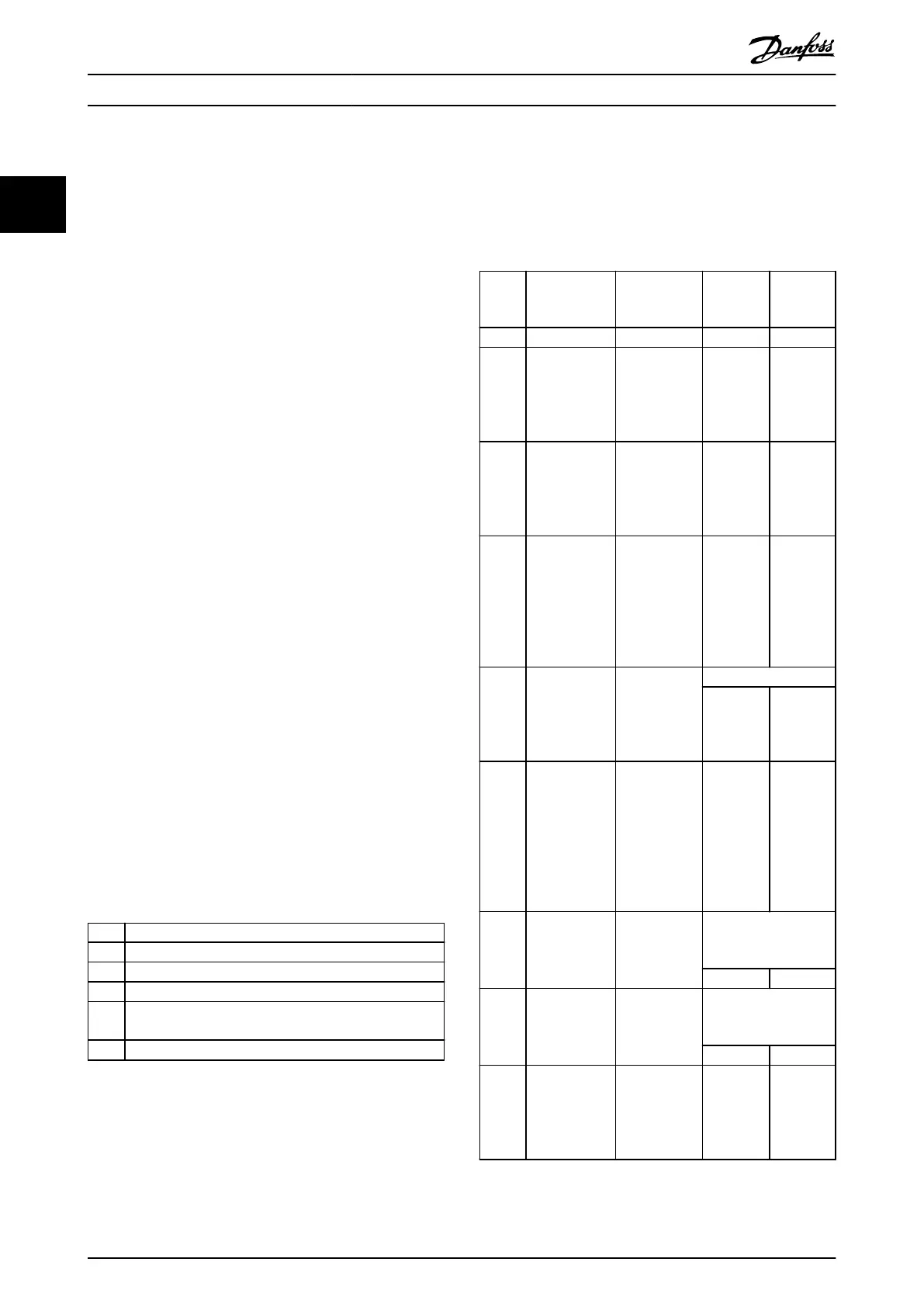
2.4.5.7 Notications from the Servo Drive
The servo drive sends out information about the currently
ongoing CAM execution or as a reaction on a command.
Bit 16 (MSB) of the status code is a toggle bit. As
synchronous eldbuses are supported, it is not possible to
distinguish between a new and a resent notication.
Therefore, the edge of the toggle bit must be monitored.
The CAM status information is represented in 4 16-bit
objects (see chapter 7.14.2 Parameter: CAM Status (0x3801)).
One of them is the status code, whereas the rest contains
additional information (see Table 2.56).
Status
code
Meaning Status
parameter
1
Status
parameter
2
Status
parameter
3
0x0000 Reserved Reserved Reserved Reserved
0x0002 Result of
dynamic
alignment
SegmentID of
alignment
segment
(pattern or
mark)
1: Success
0: Failure
Reserved
0x0004 Following error
(also signaled
in the
Statusword)
SegmentID of
the segment
in which the
following error
occurred
Reserved Reserved
0x0005 Node/data
point passed
nodeID/data
point that was
passed
SegmentID
of current
segment/n
ot
available
for basic
CAM
Reserved
0x0006 Bad parameter
sent to a
segment or
segment does
not exist
Sent
SegmentID
Sent parameter [oat]
Low byte High byte
0x0007 Bad parameter
sent: Error
when setting
following
segment of a
node (node or
segment not
valid)
Sent
SegmentID
Sent
nodeID
Reserved
0x0009 Correction
angle
indication
ID of MoveDis-
tanceSegment
Logical rotor angle
[oat; given in
revolutions]
Low byte High byte
0x000A Flying stop
angle
indication
ID of Flying-
StopSegment
Logical rotor angle
[oat; given in
revolutions]
Low byte High byte
0x000B Forced Time-
exit;
EventSegment-
Container too
short
ID of EventSeg-
mentContainer
Reserved Reserved
Table 2.56 CAM Control Data Information
Servo Drive Operation
VLT
®
Integrated Servo Drive ISD
®
510 System
76 Danfoss A/S © 01/2017 All rights reserved. MG36D102
22
 Loading...


