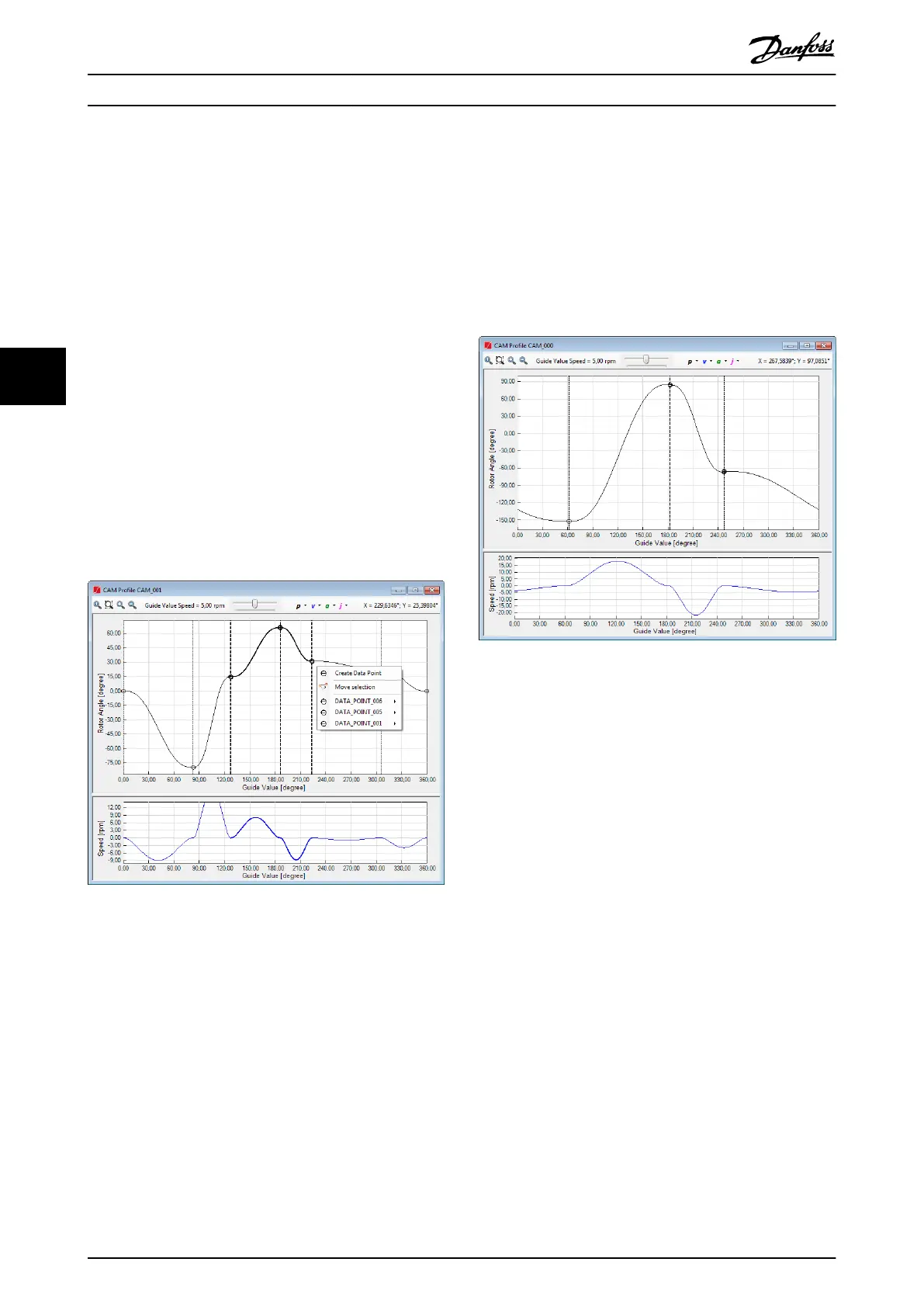
If 1 or more data points have been selected and there is a
right-click on any location, or if there are no selected data
points but a right-click on a data point, the extended basic
CAM context menu is displayed, as shown in
Illustration 5.66.
The extended basic CAM context menu contains the
following elements:
•
Create data point
•
Move selection
- This is only visible when multiple data
points are selected.
- It shows a window for typing in a delta
X value and delta Y value for all selected
points and moves the points as
specied.
For each selected data point, a submenu that is named
after the data point (for example, DATA_POINT_006 in
Illustration 5.66) is shown. This contains the following entry:
•
Move…: Has the same functionality as the Move
selection element, however it is only applied to
the selected data point.
Illustration 5.66 Context Menu for Multi-Selection
Sanity check
The Sanity check functionality for basic CAM proles
examines if there are 2 data points with the same guide
value (horizontal axis) and reports such cases.
5.7.7.7 Editing Advanced CAM Proles
The advanced CAM visualization and editing are dierent
to basic CAM mode. This section presents and describes
the advanced CAM prole editing and visualization. Further
information about advanced CAM can be found in
chapter 2.4.5.5 Advanced CAM.
Advanced CAM guide nodes only contain guide values
(master positions) and event nodes do not contain any
positioning or timing information. All other data (rotor
angle, velocity, acceleration, duration) is contained in the
advanced CAM segments.
Node and segment visualization
An advanced CAM node is visualized as a dashed vertical
line. It can be selected and moved horizontally in both
directions. Illustration 5.67 shows 3 Guide nodes and 3
Guide polys between them. The circles drawn on top of the
nodes represent the edges of the Guide poly.
Illustration 5.67 Advanced CAM Mode: Guide Nodes and Guide
Polys
Prole properties
Advanced CAM proles have the following properties:
•
Prole type
•
Data
- Control parameters
•
Control set 1
- Position P
- Position D
- Speed P
- Speed I
- Speed D
- Inertia
•
Control set 2 (same as control
set 1).
- Following error
•
Window
•
Time
- Scaling
•
Master scaling
Operation with ISD Toolbox
VLT
®
Integrated Servo Drive ISD
®
510 System
146 Danfoss A/S © 01/2017 All rights reserved. MG36D102
55

 Loading...


