- Numerator
- Denominator
•
Slave scaling
•
Numerator
•
Denominator
- Display
- Guide value velocity
- Maximum guide value velocity
- First node
- End nodes
Node properties
Advanced CAM guide nodes contain the following
properties:
•
Parameters:
- ID
- Node Type (read-only): always Guide
node
- Position
- Signal
- Actions (comma-separated action IDs)
•
Relations
- Default segment
- Preceding segments (read-only)
- Succeeding segments (read-only)
•
Appearance
- Visible
Advanced CAM event nodes contain the following
properties:
•
Parameters:
- ID
- Node type (read-only): always Event
node
- Signal
- Actions IDs
•
Relations
- Related container (read-only)
- Is starting node (read-only)
- Default segment
- Preceding segments (read-only)
- Succeeding segments (read-only)
•
Appearance
- Visible
Context menu
The context menus when editing advanced CAM proles
are the same as the ones in basic CAM mode:
•
When right-clicking on an empty area on the
rotor angle plot, the entries for creating a new
node or a new segment are shown.
•
When right-clicking on a node or segment,
entries for modication are shown.
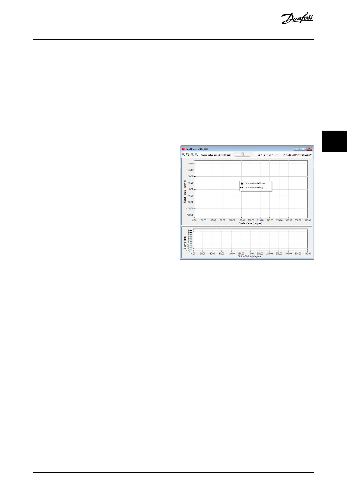
Illustration 5.68 shows the context menu for creating a
Guide node or a Guide poly that appears when right-
clicking on an empty area on the rotor angle plot.
Illustration 5.68 Advanced CAM Editing: Context Menus for
Creation
When using the context menu, it is possible to graphically
create Guide nodes and Guide polys by clicking on the
desired locations (guide value, rotor angle). The Guide polys
can be further transformed to any other guide segment
type.
Guide nodes are created in the same way as basic CAM
data points. The dierence between them is that Guide
nodes only dene a guide value position (x-coordinate),
but do not map a rotor angle to it (y-coordinate).
Therefore, only the x-coordinate of the mouse pointer is
considered when graphically creating a guide node.
A Guide poly is graphically created by specifying its
preceding and succeeding nodes, as well as its start and
end rotor angles, via 1 of the following 2 methods:
•
It can be created for 2 already existing guide
nodes by clicking on the node at the desired
rotor angle level.
•
By using the left mouse button to plot the new
Guide poly with the desired start and end rotor
angles, which simultaneously creates the relevant
guide nodes.
After selecting the Create Guide Poly item from the context
menu, only 2 clicks are required to dene a Guide poly: The
Operation with ISD Toolbox Programming Guide
MG36D102 Danfoss A/S © 01/2017 All rights reserved. 147
5 5

 Loading...


