2.3 Basic Operation
2.3.1 State Machine
The servo drive uses the state machine described in the CiA DS402 standard. The state machine is operated either locally via
the LCP or remotely via the network.
The state machine is operated by local signals and by the Controlword sent over the eldbus. The state of the state machine
is reported by the Statusword produced by the servo drive.
A single state represents a special internal or external behavior. The state of the state machine also determines which
commands are accepted.
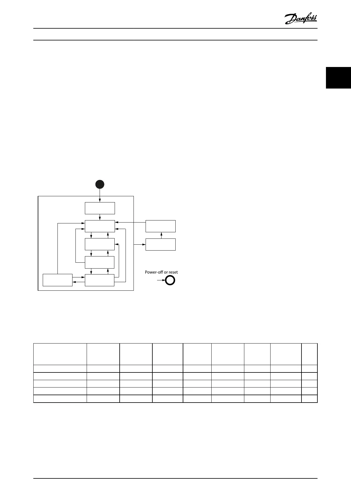
Illustration 2.1 shows the state machine of the servo drive with regard to control of the power electronics as a result of
commands and internal servo drive faults.
Start
Not ready to
switch on
Switch on
disabled
Fault
Fault reaction
active
Ready to
switch on
Switched on
Operation
enabled
Quick stop
active
0
1
2 7
8 9
63
4 5
16
11
10
12
13
15
14
Illustration 2.1 DS402 State Machine
The states support the functions shown in Table 2.1. The Start state is a pseudo state indicating the start when the state
machine is activated during the start-up sequence of the device drives application software.
Function
Not ready to
switch on
Switch on
disabled
Ready to
switch on
Switched on
Operation
enabled
Quick stop
active
Fault
reaction
active
Fault
Brake applied, if present Yes Yes Yes Yes No No No Yes
Low-level power applied Yes Yes Yes Yes Yes Yes Yes Yes
High-level power applied Yes/no Yes/no Yes/no Yes Yes Yes Yes Yes/no
Drive function enabled No No No No Yes Yes Yes No
Conguration allowed Yes Yes Yes Yes Yes Yes Yes Yes
Table 2.1 DS402 States and Supported Functions
Quick stop active state is implemented, which is optional according to the standard. When entering this state, the behavior
of the servo drive is according to the option code
dened in object 0x605A (see chapter 7.20.6 Parameter 50-46: Quick Stop
Option Code (0x605A)).
Servo Drive Operation Programming Guide
MG36D102 Danfoss A/S © 01/2017 All rights reserved. 19
2 2

 Loading...


