The transition from state Quick stop active to state Operation enabled (Transition 16 in Illustration 2.1) is not available, as
recommended by the standard.
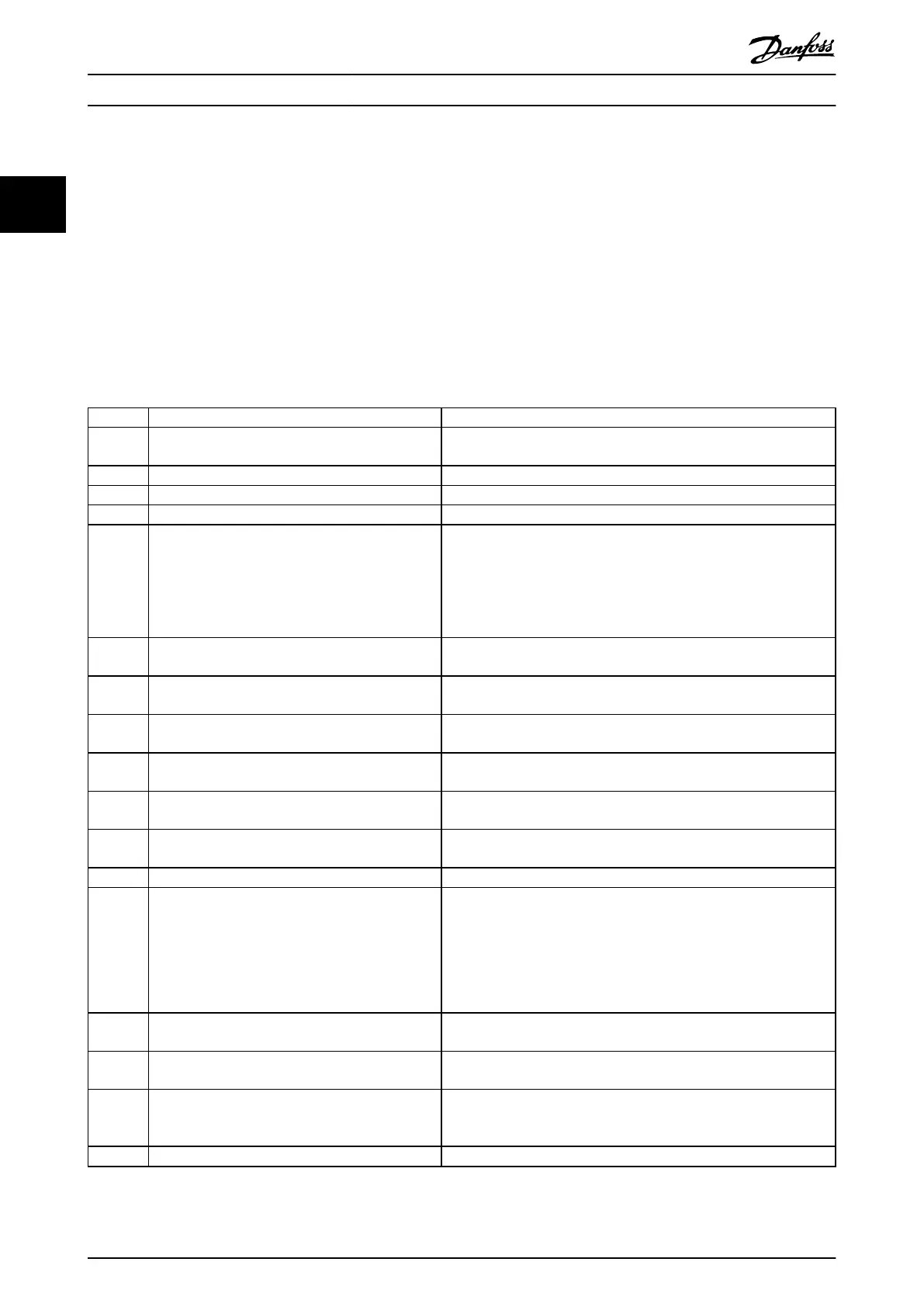
The servo drive supports the transitions and actions as given in Table 2.2. The events initiate the transition. The transition is
terminated after the action has been performed.
High-level power applied means that UDC is applied at the input of the servo drive. Yes/No means that it is allowed but not
necessary.
Conguration allowed means that the following conguration is allowed:
•
Changes to the option code objects (see chapter 7.20 Option Code Objects).
•
Changes to the mode of operation object (see chapter 7.5.1 Parameter 52-00: Modes of Operation (0x6060)).
Transition Event Action
0 Automatic transition after power-on or reset
application.
Servo drive self-test and self-initialization are performed.
1 Automatic transition. Communication is activated.
2 Shutdown command received from control device. –
3 Switch on command received from control device. High-level power is switched on, if possible.
4 Enable operation command received from control
device.
The servo drive function is enabled and all internal setpoints are
cleared.
If the servo drive is rotating when the command to carry out transition
4 is received, the behavior is dened by option code
chapter 7.20.4 Parameter 50-44: Enable in Positioning Option Code
(0x2052).
5 Disable operation command received from control
device.
The congured disable operation reaction function is executed (see
chapter 7.20.9 Parameter 50-49: Disable Operation Option Code (0x605C)).
6 Shutdown command received from control device. The congured shutdown reaction function is executed (see
chapter 7.20.8 Parameter 50-48: Shutdown Option Code (0x605B)).
7 Quick stop or disable voltage command received
from control device.
–
8 Shutdown command received from control device. The servo drive function is disabled and high-level power is switched
o, if possible.
9 Disable voltage command received from control
device.
The servo drive function is disabled and high-level power is switched
o, if possible.
10 Disable voltage or quick stop command received
from control device.
High-level power is switched o, if possible.
11 Quick stop command received from control device. The quick stop function is started.
12 Automatic transition when:
•
Quick stop function is completed (see
chapter 7.20.6 Parameter 50-46: Quick Stop Option
Code (0x605A)).
•
Disable voltage command received from control
device.
The congured quick stop reaction function is executed (see
chapter 7.20.6 Parameter 50-46: Quick Stop Option Code (0x605A)).
13 Fault signal. The congured fault reaction function is executed (see
chapter 7.20.1 Parameter 50-41: Fault Reaction Option Code (0x605E)).
14 Automatic transition. The servo drive function is disabled and high-level power is switched
o, if possible.
15 Fault reset command received from control device. If no fault exists on the servo drive, the fault condition is reset. After
leaving state Fault, clear the fault reset bit in the Controlword via
eldbus or the LCP.
16 Not supported. –
Table 2.2 Transition Events and Actions
Servo Drive Operation
VLT
®
Integrated Servo Drive ISD
®
510 System
20 Danfoss A/S © 01/2017 All rights reserved. MG36D102
22

 Loading...


