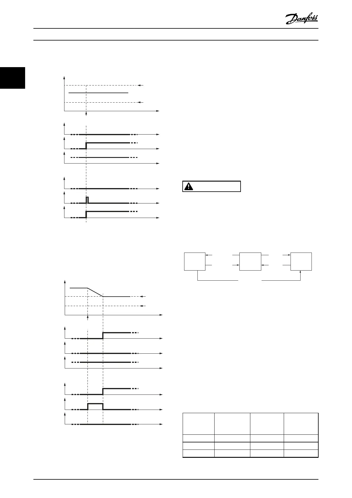
Target
reached
Position
Command
Error
Positive software
limit active
Done
PLC
Fieldbus
Busy
Error
Positioning
command
Target
position
Software
position limit
Time
130BF164.10
Illustration 2.8 Servo Drive is Outside the Valid Position Limit
and the Target Position is in the Wrong Direction
Target
reached
Position
Command
Error
Positive software
limit active
Done
PLC
Fieldbus
Busy
Error
Time
Target
position
Software
position limit
Positioning
command
130BF165.10
Illustration 2.9 Servo Drive is Outside the Valid Position Limit.
The Target Position is Still Not in a Valid Area, but is Nearer to
it than the Previous Position
2.3.5 Brake Handling
When the servo drive enters state Operation enabled, it
automatically lifts the brake. The servo drive reports the
new state after the brake is lifted.
When the servo drive leaves state Operation enabled, it
automatically releases the brake so that the axis cannot
sag down. The servo drive reports the new state after the
brake is unreleased.
The brake state can be overwritten using the digital output
object (see chapter 7.21.4 Parameter 16-66: Digital Outputs
(0x60FE)). This is only allowed in unpowered state. The
valid commands and the reactions are shown in
Illustration 2.10.
WARNING
UNINTENDED MOTION
Releasing the brake in an unpowered state may result in
unintended motion leading to death, serious injury,
damage to equipment, or other material damage.
•
Do not release the brake in an unpowered state.
Motor in
unpowered
state
Brake is open
Motor in
unpowered
state
Brake is closed
Motor is
energized
Brake is open
User command:
Close brake
Energize
motor
Unpower
motor
User command:
Open brake
Energize motor
Illustration 2.10 Valid Brake Commands and Reactions
It is not possible to have an energized motor with a closed
brake. For further information about the current state, see
chapter 7.22.8 Parameter 50-09: STO Voltage and Brake Status
(0x2007).
2.3.6 Control Loops
Servo motor control takes place using 3 cascaded control
loops (position controller, speed controller, and current
controller) with trajectory generators for position and
velocity. The control loops run synchronously with the
eldbus cycles. The cycle times shown in Table 2.3 are
possible with Ethernet POWERLINK
®
and EtherCAT
®
:
Fieldbus cycle
[µs]
Position control
cycle
[µs]
Speed control
cycle
[µs]
Current control
cycle
[µs]
400 200 200 100
500 250 250 125
800 200 200 100
Servo Drive Operation
VLT
®
Integrated Servo Drive ISD
®
510 System
24 Danfoss A/S © 01/2017 All rights reserved. MG36D102
22

 Loading...


