Fieldbus cycle
[µs]
Position control
cycle
[µs]
Speed control
cycle
[µs]
Current control
cycle
[µs]
1000 250 250 125
Table 2.3 Ethernet POWERLINK
®
and EtherCAT
®
Cycle Times
The used cycle times can be read using object 0x201D (see
chapter 7.6.1 Parameter 51-07 to 51-09: Used Task Cycle
Times (0x201D)). The values are given in microseconds.
There are 2 control parameter sets in the servo drive,
however only 1 of them can be active at any time. Use bit
15 (cs) in the Controlword to switch from 1 set to the other.
Linear blending occurs from the parameter of the currently
active set to the new one. The blending time is dened in
object 0x201B (see chapter 7.6.2 Parameter 51-01: Control
Parameter Blending Time (0x201B)).
No blending takes place when writing to a value of the
currently active control parameter set. The new value is
used immediately, which could cause a jerk on the shaft.
Blending is used when updating a whole set of parameters
at the same time (for example, when activating CAM mode,
which uses its own sets of control parameters).
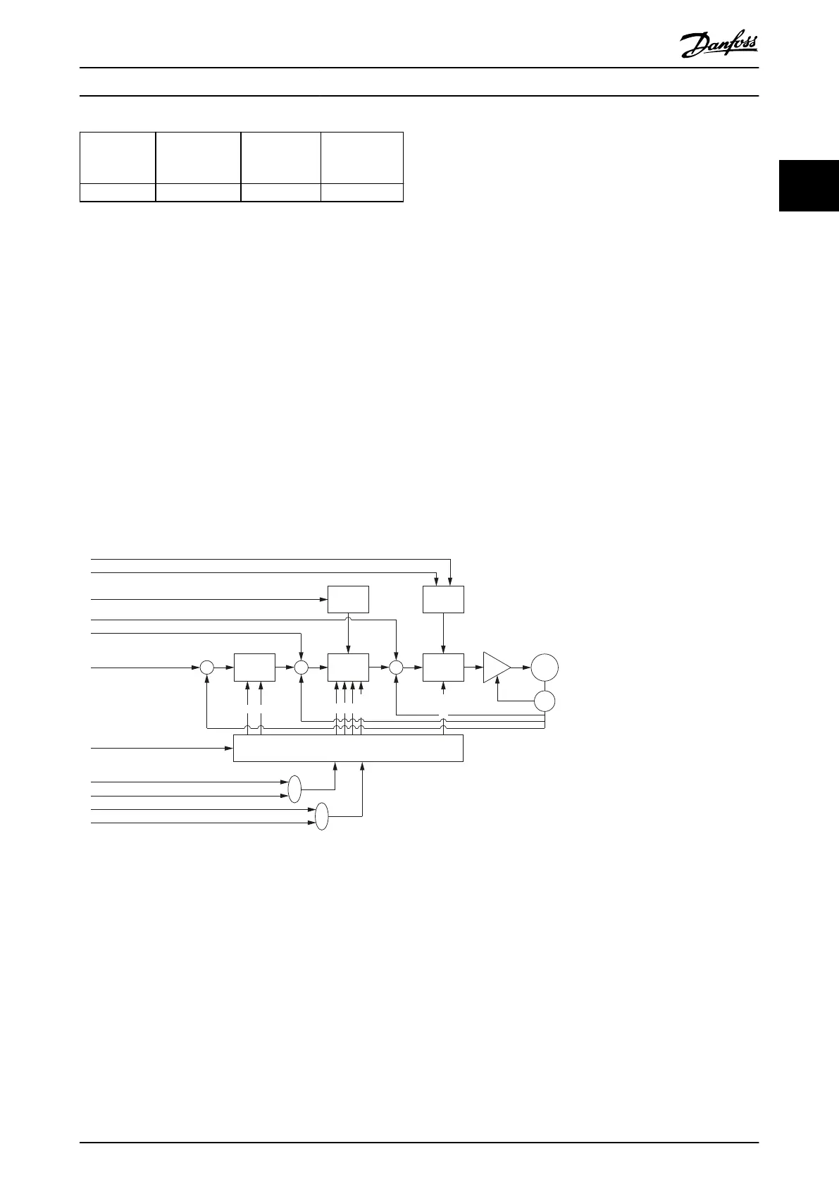
2.3.6.1 Position Controller
The controller uses PD control. The D constant is the derivative time constant. The controller provides 2 sets of control
parameters that can be switched during operation (see chapter 7.7.8 Parameters 51-02, 52-04, and 52-49: Application Settings
(0x2016) and chapter 7.6.4.2 Parameters 51-26 and 51-27: Position Controller Parameters 2 (0x2015)).
Both sets are available as read-write objects in the object dictionary. Use a manufacturer-specic bit in the Controlword to
switch between the 2 sets of parameters.
Limit
function
Limit
function
Torque
control
Velocity
control
Position
control
Selector
Application torque limit (0x2053)
Max torque (0x6072)
Max motor speed (0x6080)
Feed forward torque
Feed forward velocity
Position demand
Internal value (0x60FC)
Controlword (0x6040)
Position controller parameters (0x2013)
Speed controller parameters (0x2012)
Position controller parameters 2 (0x2015)
Speed controller parameters 2 (0x2014)
+
+
+
+
– – –
+
P D
P D
Notch
Inertia
M
S
Illustration 2.11 Position Control Loop
Servo Drive Operation Programming Guide
MG36D102 Danfoss A/S © 01/2017 All rights reserved. 25
2 2

 Loading...


