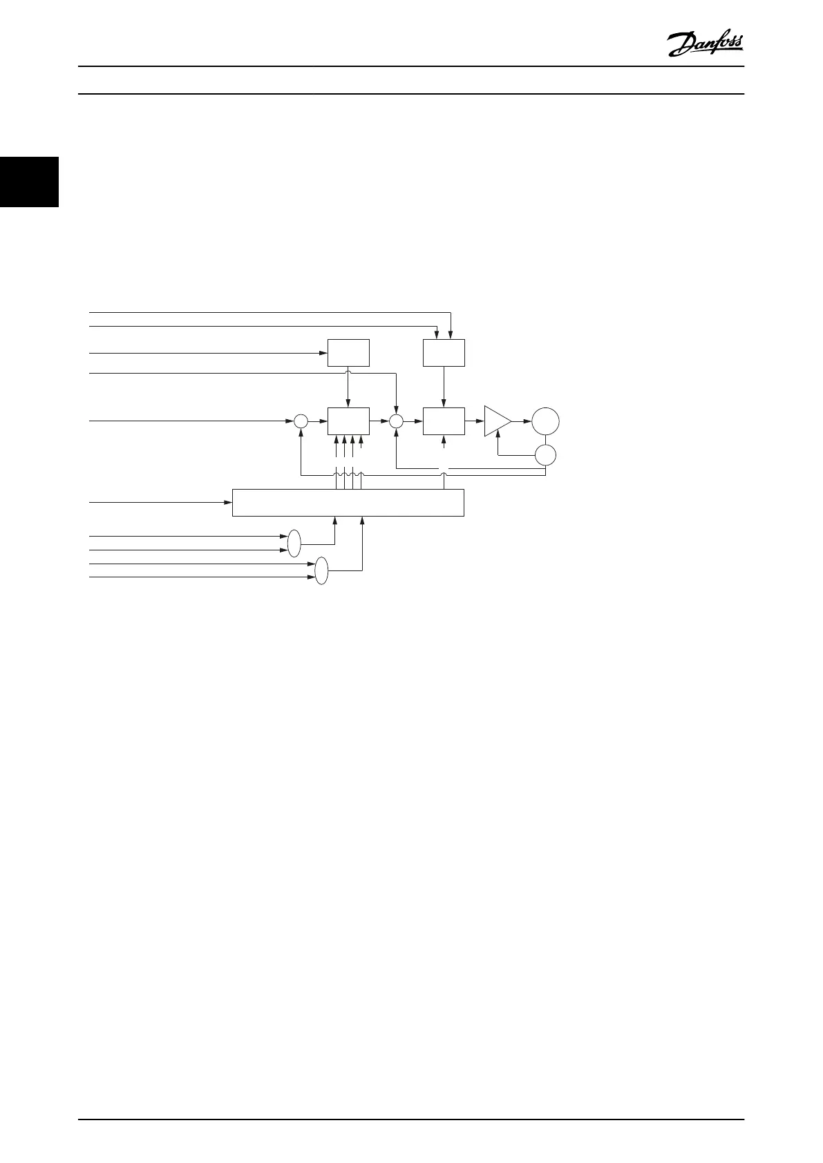
2.3.6.2 Speed Controller
The controller uses PID control. The D constant is the derivative time constant. The speed controller has a Notch-Filter (IIR)
that can be parameterized (center frequency/bandwidth) to suppress resonance. The controller provides 2 sets of control
parameters (see chapter 7.6.5.1 Parameters 51-10 to 51-15: Speed Controller Parameters (0x2012) and chapter 7.6.5.2 Parameters
51-20 to 51-25: Speed Controller Parameters 2 (0x2014)) that can be switched spontaneously.
Both sets are available as read-write objects in the object dictionary. Use a manufacturer-specic bit in the Controlword to
switch between the 2 sets of parameters.
Limit
function
Limit
function
Torque
control
Velocity
control
Selector
Application torque limit (0x2053)
Max torque (0x6072)
Max motor speed (0x6080)
Feed forward torque
Feed forward velocity
Controlword (0x6040)
Position controller parameters (0x2013)
Speed controller parameters (0x2012)
Position controller parameters 2 (0x2015)
Speed controller parameters 2 (0x2014)
+ +
+
– –
P D
Notch
Inertia
M
S
Illustration 2.12 Speed Control Loop
2.3.6.3 Current Controller
The current controller runs synchronous to the eldbus cycle time. It cannot be parameterized.
2.4
Operating Modes
The servo drive implements several modes of operation. The behavior of the servo drive depends on the activated mode of
operation. It is possible to switch between the modes while the servo drive is enabled. The supported modes of operation
are according to CANopen
®
CiA DS402 and there are also ISD-specic modes of operation. All supported modes of
operation are available for EtherCAT
®
and Ethernet POWERLINK
®
.
2.4.1 Prole Position Mode
In Prole position mode, the servo drive is operated under position control and executes absolute and relative movements.
Parameters such as velocity, acceleration, and deceleration can be parameterized. The servo drive provides a buer to queue
a following move while another move is already executing.
This functionality can be commanded using the function blocks MC_MoveAbsolute_ISD51x (see chapter 6.5.5.4 MC_MoveAb-
solute_ISD51x) and MC_MoveRelative_ISD51x (see chapter 6.5.5.5 MC_MoveRelative_ISD51x). This functionality can also be
used via the LCP (see section Position mode in chapter 4.3.5.1 Servo Drive).
When switching to Prole position mode from Prole velocity mode, CAM mode, Gear mode, or Prole torque mode, the servo
drive continues rotating with the current velocity. As soon as there is a new setpoint (handed over using the handshaking
between Controlword and Statusword), the new setpoint is processed with the corresponding parameters.
Servo Drive Operation
VLT
®
Integrated Servo Drive ISD
®
510 System
26 Danfoss A/S © 01/2017 All rights reserved. MG36D102
22

 Loading...


