When switching from a torque or velocity controlled mode to Prole position mode, the last target position is set to the
position actual value. This is relevant when starting a relative movement from the last target position after switching to this
mode, because no last target position from the previous mode is available. If the previous mode ended with a velocity
unequal to 0, the last target position is the position actual value at the time of the mode switch.
If the trajectory is completed (target position is reached) and the end velocity (see chapter 7.10.2 Parameter 52-16: End
Velocity (0x6082)) is unequal to 0, the servo drive continues rotating at the specied end velocity until a further trajectory is
set.
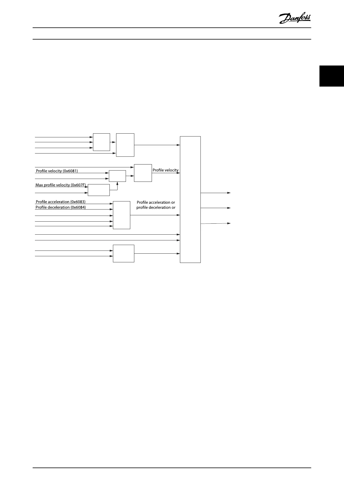
Tragectory
generator
Minimum
comparator
Minimum
comparator
Limit
function
Limit
function
Limit
function
Multiplier
Multiplier
Target position (0x607A)
Position range limit (0x607B)
Software position limit (0x607D)
Drive mirror mode (0x2016, 02)
Drive mirror mode (0x2016, 02)
End velocity (0x6082)
Max motor speed (0x6080)
Quick-stop deceleration (0x6085)
Max acceleration (0x60C5)
Quick-stop option code (0x605A)
Positioning option code (0x60F2)
Max torque (0x6072)
Application torque limit (0x2053)
Torque limit
Position demand
internal value
(0x60FC)
Feed forward
velocity
Feed forward
torque
Max deceleration (0x60C6)
quick-stop deceleration
Target position
Velocity limit
or End velocity
Illustration 2.13 Prole Position Mode Control Function
Target position activation
The activation of a setpoint is controlled by the timing of:
•
The new setpoint bit and the change set immediately bit in the Controlword.
•
The setpoint acknowledge bit in the Statusword.
If the Change set immediately bit of the Controlword is set to 1, a potentially ongoing motion is interrupted and the new
setpoint is used immediately. If the Change set immediately bit of the Controlword is set to 0, the ongoing positioning
command is nished rst and the new setpoint is executed afterwards.
After a setpoint is applied to the servo drive, the control device signals that the setpoint is valid by a rising edge of the new
setpoint bit in the Controlword. The servo drive sets the setpoint acknowledge bit in the Statusword to 1. Afterwards, the
servo drive with the setpoint acknowledge bit set to 0 signals its ability to accept new setpoints. An example is shown in
Illustration 2.14.
Servo Drive Operation Programming Guide
MG36D102 Danfoss A/S © 01/2017 All rights reserved. 27
2 2

 Loading...


