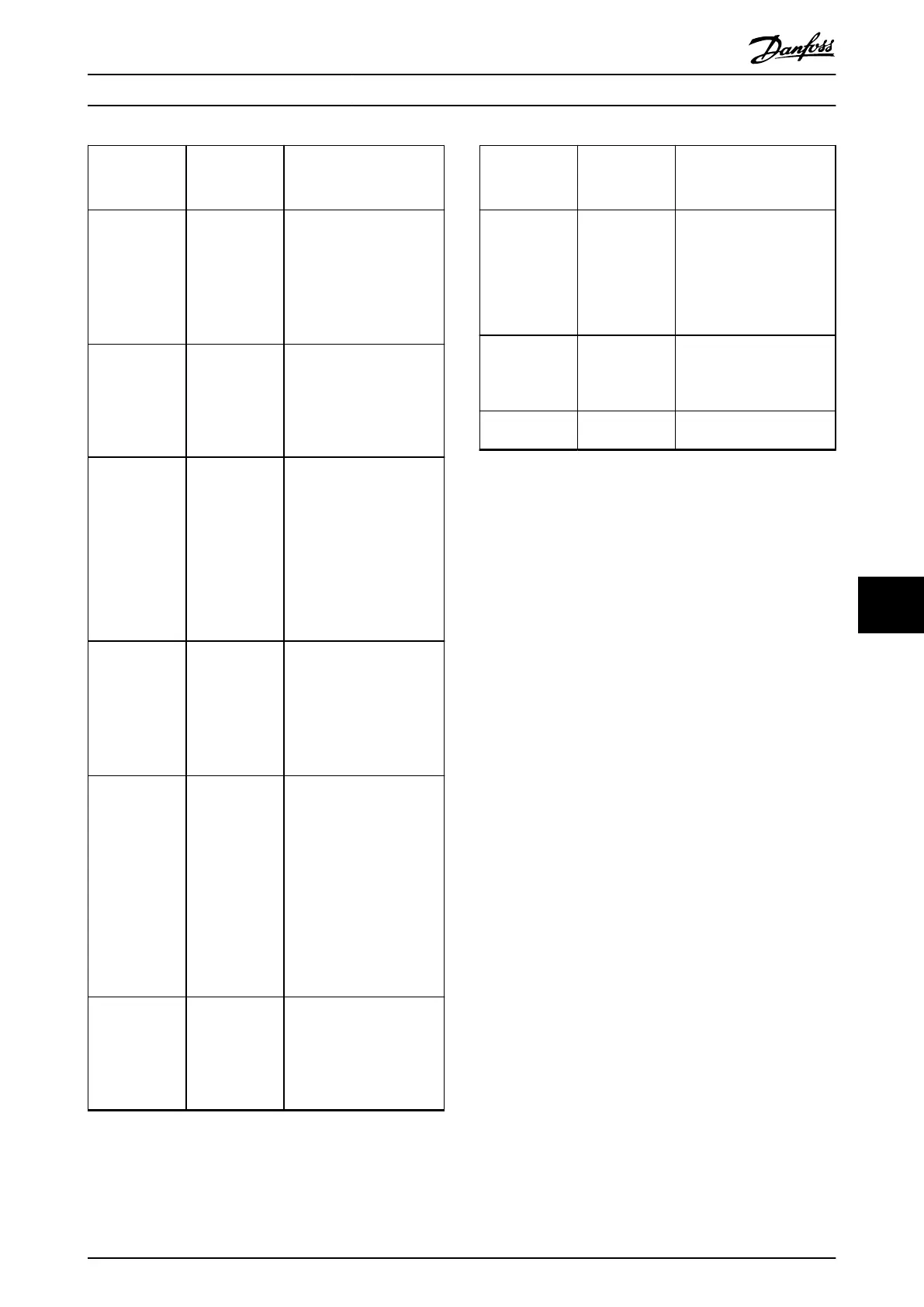
Fault Possible cause Possible solution
DC-link voltage
too low.
Incorrect mains
supply.
Check supply voltage
matches the allowed speci-
cation detailed in chapter
ISD Safety Concept in the
VLT
®
Integrated Servo Drive
ISD
®
510 System Operating
Instructions.
DC overcurrent. The sum of the
servo drive
current exceeds
the maximum
rating of the
SAB.
•
Check the servo drive
current consumption.
•
Avoid simultaneous
acceleration of all servo
drives.
U
AUX
overcurrent. The servo drives
are consuming
more power on
the U
AUX
line
than allowed.
•
Check the number of
attached servo drives
with the shell diagrams
in the VLT
®
Integrated
Servo Drive ISD
®
510
System Design Guide.
•
Avoid simultaneous
lifting of the servo drive
brakes.
U
AUX
overvoltage.
Incorrect U
AUX
supply.
Check that the supply
matches the allowed speci-
cation detailed in chapter
Electrical Installation in the
VLT
®
Integrated Servo Drive
ISD
®
510 System Operating
Instructions.
U
AUX
undervoltage.
Incorrect U
AUX
supply.
•
Check that the supply
matches the allowed
specication detailed in
chapter Electrical Instal-
lation in the VLT
®
Integrated Servo Drive
ISD
®
510 System
Operating Instructions.
•
Check that the output
power of the supply is
sucient.
Mains phase
loss.
A phase is
missing on the
supply side, or
the voltage
imbalance is too
high.
Check the supply voltages
and supply currents to the
SAB.
Fault Possible cause Possible solution
Grounding fault. Grounding fault.
•
Check for proper
grounding and loose
connections.
•
Check the hybrid cables
for short circuits or
leakage currents.
Brake resistor
error.
Faulty brake
resistor.
Remove the power to the
SAB, wait for the discharge
time to elapse, then replace
the brake resistor.
Brake chopper
error.
Faulty brake
chopper.
Check the setting in
parameter 2-15 Brake Check.
Table 9.4 Troubleshooting SAB
Diagnostics Programming Guide
MG36D102 Danfoss A/S © 01/2017 All rights reserved. 373
9 9

 Loading...


