Attribute
Mandatory/
optional
(+default
value)
Value range/
allowed values
Description
input M 1/2 Selects if the
1
st
or the 2
nd
digital input
counter is
aected.
Table 2.43 Attributes for stopCounter
The counter values can be read from the object 0x3860
(see chapter 7.14.17 Parameter: Digital Input Counters
(0x3860)). The values are read/write for manually modifying
the counters.
Action: Set Follow Segment
Instructs the servo drive to change the used succeeding
segment of a node. It is only possible to select a segment
ID that has this node ID
dened as preceding node. This
change is preserved over the guide value cycles, so no
automatic switching back takes place.
<setFollowSegment nodeID="1" segID="2"/>
Attribute
Mandatory/
optional
(+default
value)
Value range/
allowed values
Description
nodeID M An existing
node ID.
The mode ID
to get another
following
segment.
When using a
non-existing
nodeID, a
notication
from the axis is
sent.
segID M An existing
segment ID.
The segment
ID that will be
processed after
the specied
node. When
using a non-
existing segID,
a notication
from the axis is
sent.
Table 2.44 Attributes for setFollowSegment
Exit conditions
The following exit conditions are used to monitor several
variables. The axis proceeds with the next segment as soon
as the condition is met. Exit conditions can only be dened
for EventSegments.
An exit condition is described with a surrounding element
to dene an exitID which is used for referencing inside the
CAM prole. This exitID must be unique across all dened
exit conditions. Inside this exit element, there can be 1 or
more subelements. Available exit conditions are listed in the
following sub-chapters.
<exit exitID="0">
… specic exit condition(s) with corresponding attributes
<exit>
Exit: Rectangle Mark Detection
This exit condition is used to start the search for a
rectangle mark, using the sensor interface. This exit
condition is used for alignment, depending on a sensor
signal. When using this exit condition, the axis waits for a
rectangle input on the sensor interface with a length
between the specied minimum and maximum.
When using an analog sensor, a threshold for the height of
the impulse must be dened. Positive and negative
impulses can be processed. This equates to light and dark
marks with optical sensors. The axis proceeds with the next
segment as soon as the impulse is found or the maximum
duration of the segment is reached.
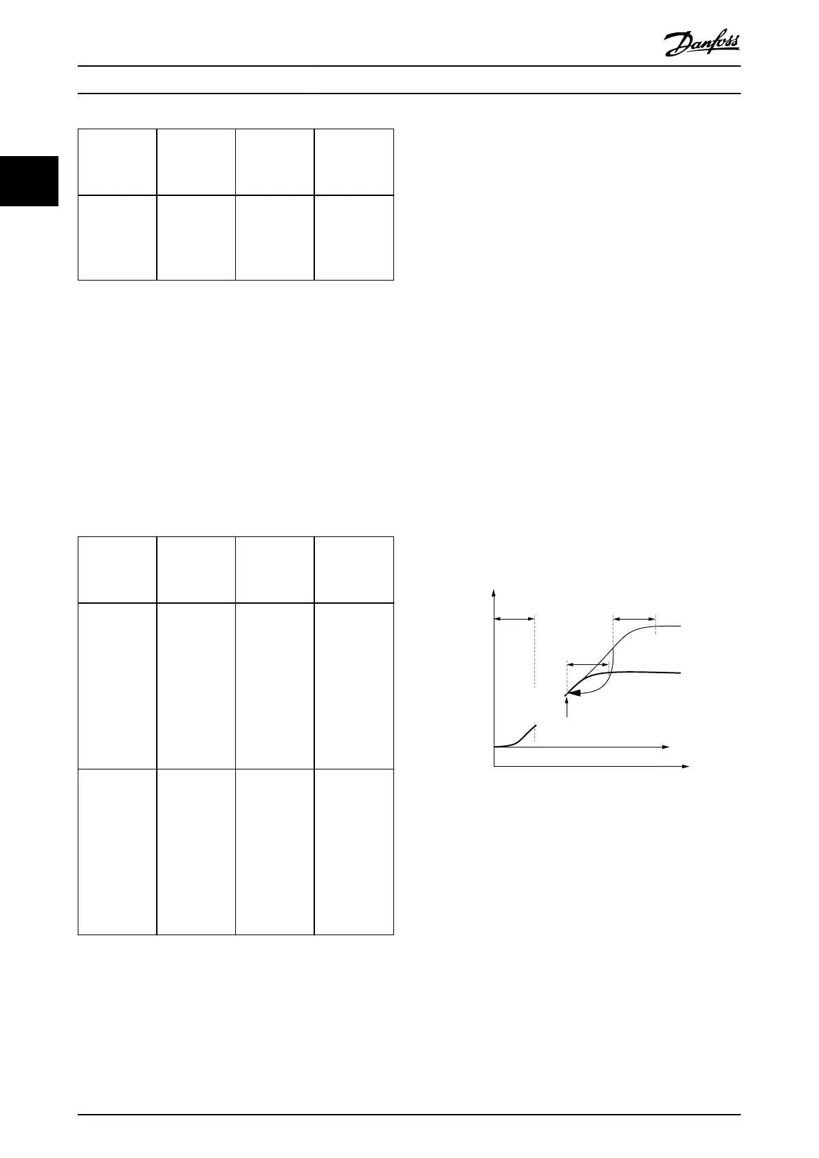
If the mark has been found and the following segment is a
braking segment (TimePoly which leads to a standstill), the
servo drive always stops at the same distance to the mark.
130BF260.10
Accelerating
phase
Rotor angle
Decelerating
phase
Decelerating
phase
Guide value
Time
Mark
found
Constant plate speed
during search for
mark
Illustration 2.113 Behavior when Mark was Found
The time at which the mark is found depends on the
position of the mark. The black line shows an example for
the case that the mark is found right at the point in time
that is marked with the black arrow.
The duration of the segment determines the latest point in
time when the search is aborted. If the mark is found
before this duration is over, the axis proceeds with the
following segment immediately after the mark is found.
Proceeding to the next segment always takes place in
relation to the middle of the impulse. To make this
possible, the point in time for proceeding depends on the
parameterized maximal length of the mark.
<rectMark input="1" mode="analogue" threshold="50"
minLength="300" maxLength="400"/>
Servo Drive Operation
VLT
®
Integrated Servo Drive ISD
®
510 System
72 Danfoss A/S © 01/2017 All rights reserved. MG36D102
22

 Loading...


