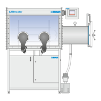
2 Inert gas technology
Components
Page
2 - 10
MB-20-G/MB-200G-W_MB-LABmaster_MB-200 MOD_TP700
Operating Manual - V5.0 - 04/2018 - STD
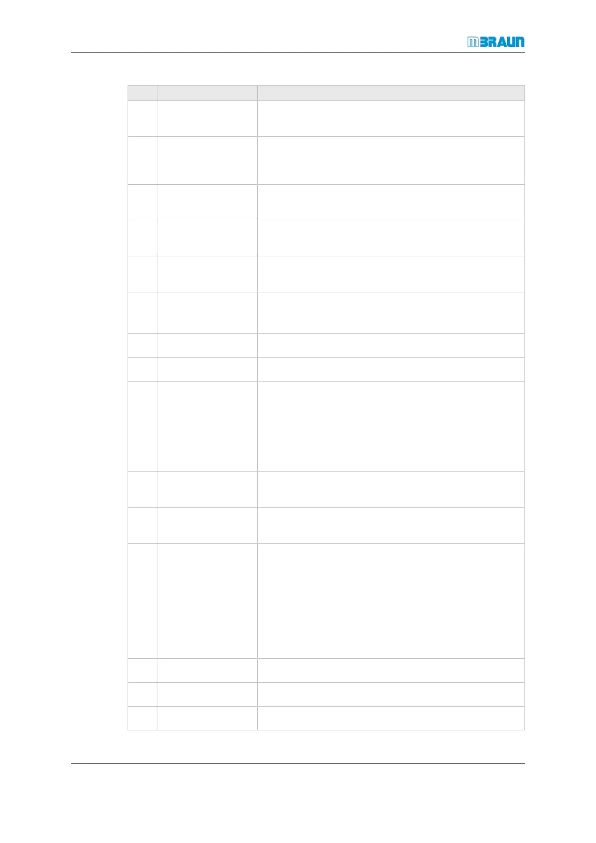
No. Component Function
1 Electrical cabinet Includes the electrical main connection, the connections
to the peripheral units and the system control.
2 Valve block Different electromagnetic valves control the purification
process, the regeneration process, pressure regulation
and further optional functions.
3 Manual adjustment
valve
Optional with box purge feature: valve for adjusting the
gas flow for the glovebox purge.
4 Exhaust Exhaust outlet for working gas to an in-house disposal
system.
5 Gas outlet pipe Gas outlet from the gas purifier to the glovebox/enclos-
ure.
6 Control gas outlet Control gas supply to external pneumatic valves
(antechamber and glovebox/enclosure).
7 3-way valve Inertisation of the solvent filter after exchange
8 Manometer Inertisation of the solvent filter after exchange
9 Heat exchanger Equipment to cool down the circulating gas.
The working gas is heated in the gas purifier by chemical
processes as well as by mechanical energy. The heat ex-
changer cools the working gas. In this manner, a con-
venient temperature inside the glovebox/enclosure is
maintained.
10 Circulation blower Exhausts contaminated gas out of the box or enclosure
and pushes the gas back as purified gas.
11 Vacuum pump Used for glovebox/enclosure pressure control, antecham-
ber cycles and regeneration cycles.
12 Media connections Connection plate for:
¡ Power for gas purifier and vacuum pump
¡ Working gas
¡ Regeneration gas
¡ Drain water
¡ Cooling water
13 Discharge opening To discharge exhausted activated carbon.
14 Refill opening To refill new, fresh activated carbon.
15 Gas inlet pipe Gas inlet from the glovebox/enclosure to the gas purifier.