To see which technology option your servo drive features (if any), go to ►Project tree
►Drive Settings ►Device description in Moog DRIVEADMINISTRATOR and check
“Technology option” in the “Hardware” section.
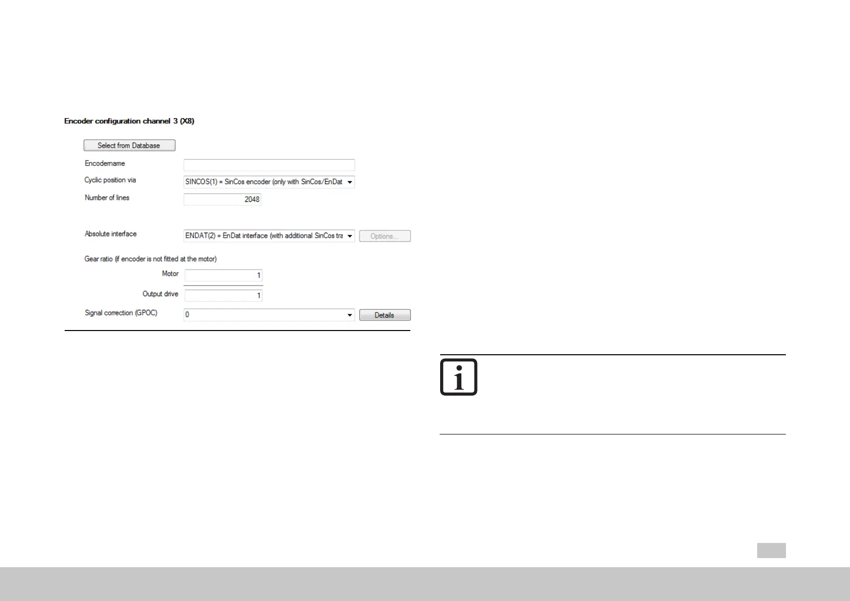
Fig. 6.5: Encoder configuration channel 3 (X8) dialog box
This screen is used to select the encoder for channel Ch3. This channel uses the
encoder’s “main interface” to measure position changes periodically and add them
up cyclically – what is referred to as “cyclical evaluation”.
Encoders with a main interface that only makes it possible to measure the cyclical
position incrementally often feature an additional absolute value interface referred to
as an “auxiliary interface”. For this interface, the absolute position is measured once
during the initialization phase and is then used for absolute value initialization
purposes.
MOOG
ID
No.: CB40859-001 Date: 02/2018
MSD Servo Drive- Device Help
77
6 Encoder
Select from database
Clicking on this button will open a menu that can be used to select encoders. The
data sets for Moog encoders will already be available there by default.
Encoder name
You can use this field to enter your own information for describing the encoder
(maximum 31 characters) (P580[0] - ENC_CH3_Info).
Cyclic position via
This drop-down menu is used to select the “main interface” (P507[0] - ENC_CH3_
Sel).
Pulses per revolution
As soon as SINCOS(1), TTL(3) or TTL_COM(5) is selected as the “main interface,”
this field will appear so that you can enter the number of analog Sin/Cos lines per
revolution (TTL lines as well).
Absolute interface
This drop-down menu is used to select the “auxiliary interface” (P570[0] - ENC_
CH3_Abs).
NOTE
Selectingan“auxiliaryinterface”isredundantif,forexample,SSI
(2)isselectedasthe“maininterface”(correspondstocyclical
evaluationviaSSI).Inthiscase,theabsolutevalueinitialization
willalsobecarriedoutviatheSSIinterface,regardlessofthe
selected“auxiliaryinterface”.
Gear ratio
These fields can be used to define a gear ratio for the encoder (in the output side).
For details, see Section "Encoder gearing" on page 87.

 Loading...