UM10462 All information provided in this document is subject to legal disclaimers. © NXP B.V. 2016. All rights reserved.
User manual Rev. 5.5 — 21 December 2016 384 of 523
NXP Semiconductors
UM10462
Chapter 19: LPC11U3x/2x/1x ADC
The ADC function must be selected via the IOCON registers in order to get accurate
voltage readings on the monitored pin. For a pin hosting an ADC input, it is not possible to
have a have a digital function selected and yet get valid ADC readings. An inside circuit
disconnects ADC hardware from the associated pin whenever a digital function is selected
on that pin.
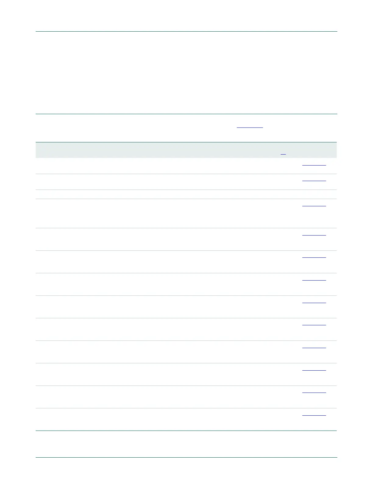
19.5 Register description
The ADC contains registers organized as shown in Table 351.
[1] Reset Value reflects the data stored in used bits only. It does not include reserved bits content.
Table 351. Register overview: ADC (base address 0x4001 C000)
Name Access Address
offset
Description Reset
Value
[1]
Reference
CR R/W 0x000 A/D Control Register. The CR register must be written to
select the operating mode before A/D conversion can occur.
0x0000 0000 Table 352
GDR R/W 0x004 A/D Global Data Register. Contains the result of the most
recent A/D conversion.
NA Table 353
- - 0x008 Reserved. - -
INTEN R/W 0x00C A/D Interrupt Enable Register. This register contains enable
bits that allow the DONE flag of each A/D channel to be
included or excluded from contributing to the generation of
an A/D interrupt.
0x0000 0100 Table 354
DR0 R/W 0x010 A/D Channel 0 Data Register. This register contains the
result of the most recent conversion completed on channel
0
NA Table 355
DR1 R/W 0x014 A/D Channel 1 Data Register. This register contains the
result of the most recent conversion completed on channel
1.
NA Table 355
DR2 R/W 0x018 A/D Channel 2 Data Register. This register contains the
result of the most recent conversion completed on channel
2.
NA Table 355
DR3 R/W 0x01C A/D Channel 3 Data Register. This register contains the
result of the most recent conversion completed on channel
3.
NA Table 355
DR4 R/W 0x020 A/D Channel 4 Data Register. This register contains the
result of the most recent conversion completed on channel
4.
NA Table 355
DR5 R/W 0x024 A/D Channel 5 Data Register. This register contains the
result of the most recent conversion completed on channel
5.
NA Table 355
DR6 R/W 0x028 A/D Channel 6 Data Register. This register contains the
result of the most recent conversion completed on channel
6.
NA Table 355
DR7 R/W 0x02C A/D Channel 7 Data Register. This register contains the
result of the most recent conversion completed on channel
7.
NA Table 355
STAT RO 0x030 A/D Status Register. This register contains DONE and
OVERRUN flags for all of the A/D channels, as well as the
A/D interrupt flag.
0 Table 356

 Loading...


