UM10462 All information provided in this document is subject to legal disclaimers. © NXP B.V. 2016. All rights reserved.
User manual Rev. 5.5 — 21 December 2016 297 of 523
NXP Semiconductors
UM10462
Chapter 14: LPC11U3x/2x/1x I2C-bus controller
SCLL and SCLH values should not necessarily be the same. Software can set different
duty cycles on SCL by setting these two registers. For example, the I
2
C-bus specification
defines the SCL low time and high time at different values for a Fast-mode and Fast-mode
Plus I
2
C.
14.7.6 I
2
C Control Clear register (CONCLR)
The CONCLR register control clearing of bits in the CON register that controls operation
of the I
2
C interface. Writing a one to a bit of this register causes the corresponding bit in
the I
2
C control register to be cleared. Writing a zero has no effect.
AAC is the Assert Acknowledge Clear bit. Writing a 1 to this bit clears the AA bit in the
CONSET register. Writing 0 has no effect.
SIC is the I
2
C Interrupt Clear bit. Writing a 1 to this bit clears the SI bit in the CONSET
register. Writing 0 has no effect.
STAC is the START flag Clear bit. Writing a 1 to this bit clears the STA bit in the CONSET
register. Writing 0 has no effect.
I2ENC is the I
2
C Interface Disable bit. Writing a 1 to this bit clears the I2EN bit in the
CONSET register. Writing 0 has no effect.
14.7.7 I
2
C Monitor mode control register (MMCTRL)
This register controls the Monitor mode which allows the I
2
C module to monitor traffic on
the I
2
C bus without actually participating in traffic or interfering with the I
2
C bus.
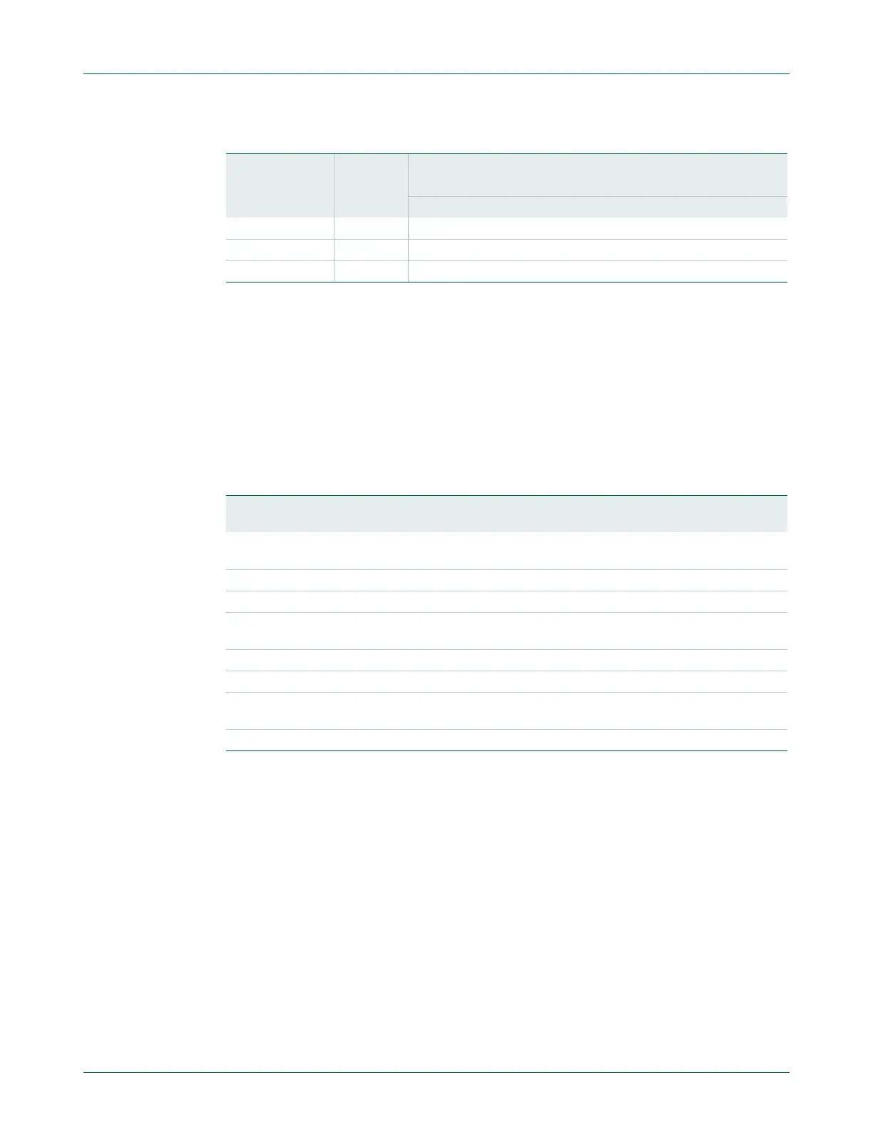
Table 277. SCLL + SCLH values for selected I
2
C clock values
I
2
C mode I
2
C bit
frequency
I2C_PCLK (MHz)
6 8 10 12 16 20 30 40 50
SCLH + SCLL
Standard mode 100 kHz 60 80 100 120 160 200 300 400 500
Fast-mode 400 kHz 15 20 25 30 40 50 75 100 125
Fast-mode Plus 1 MHz - 8 10 12 16 20 30 40 50
Table 278. I
2
C Control Clear register (CONCLR - 0x4000 0018) bit description
Bit Symbol Description Reset
value
1:0 - Reserved. User software should not write ones to reserved bits. The
value read from a reserved bit is not defined.
NA
2 AAC Assert acknowledge Clear bit.
3SIC I
2
C interrupt Clear bit. 0
4 - Reserved. User software should not write ones to reserved bits. The
value read from a reserved bit is not defined.
NA
5 STAC START flag Clear bit. 0
6I2ENCI
2
C interface Disable bit. 0
7 - Reserved. User software should not write ones to reserved bits. The
value read from a reserved bit is not defined.
NA
31:8 - Reserved. The value read from a reserved bit is not defined. -

 Loading...


