UM10462 All information provided in this document is subject to legal disclaimers. © NXP B.V. 2016. All rights reserved.
User manual Rev. 5.5 — 21 December 2016 55 of 523
NXP Semiconductors
UM10462
Chapter 3: LPC11U3x/2x/1x System control block
3.10.4 Frequency selection
The PLL frequency equations use the following parameters (also see Figure 7):
3.10.4.1 Normal mode
In this mode the post divider is enabled, giving a 50 % duty cycle clock with the following
frequency relations:
(1)
To select the appropriate values for M and P, it is recommended to follow these steps:
1. Specify the input clock frequency Fclkin.
2. Calculate M to obtain the desired output frequency Fclkout with M = F
clkout
/ F
clkin
.
3. Find a value so that FCCO = 2 P F
clkout
.
4. Verify that all frequencies and divider values conform to the limits specified in Table 9
and Table 11
.
Table 52
shows how to configure the PLL for a 12 MHz crystal oscillator using the
SYSPLLCTRL register (Table 9
). The main clock is equivalent to the system clock if the
system clock divider SYSAHBCLKDIV is set to one (see Table 23
).
3.10.4.2 Power-down mode
In this mode, the internal current reference will be turned off, the oscillator and the
phase-frequency detector will be stopped and the dividers will enter a reset state. While in
Power-down mode, the lock output will be low, to indicate that the PLL is not in lock. When
the Power-down mode is terminated by SYSPLL_PD bit to zero in the Power-down
configuration register (Table 47
), the PLL will resume its normal operation and will make
the lock signal high once it has regained lock on the input clock.
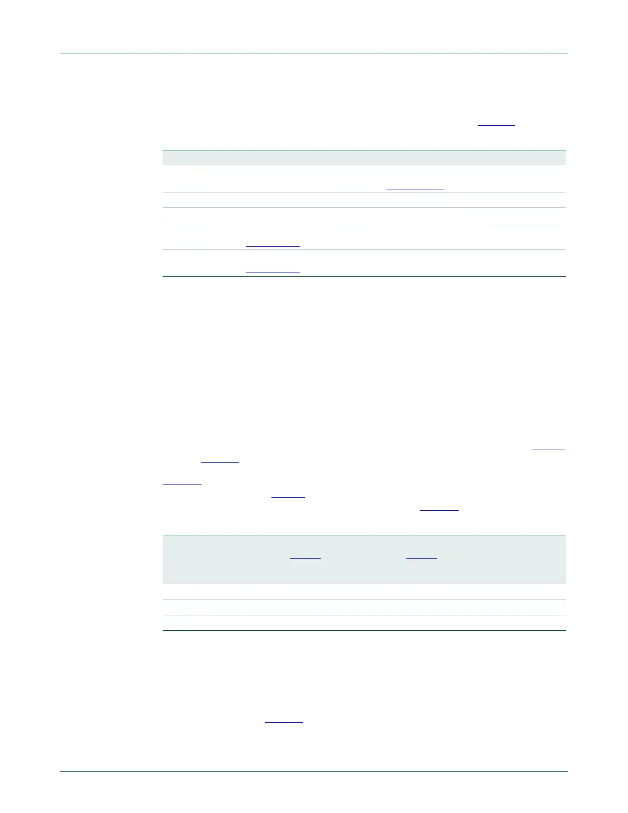
Table 51. PLL frequency parameters
Parameter System PLL
FCLKIN Frequency of sys_pllclkin (input clock to the system PLL) from the
SYSPLLCLKSEL multiplexer (see Section 3.5.11
).
FCCO Frequency of the Current Controlled Oscillator (CCO); 156 to 320 MHz.
FCLKOUT Frequency of sys_pllclkout
P System PLL post divider ratio; PSEL bits in SYSPLLCTRL (see
Section 3.5.3
).
M System PLL feedback divider register; MSEL bits in SYSPLLCTRL (see
Section 3.5.3
).
Table 52. PLL configuration examples
PLL input
clock
sys_pllclkin
(Fclkin)
Main clock
(Fclkout)
MSEL bits
Table 9
M divider
value
PSEL bits
Table 9
P divider
value
FCCO
frequency
12 MHz 48 MHz 00011(binary) 4 01 (binary) 2 192 MHz
12 MHz 36 MHz 00010(binary) 3 10 (binary) 4 288 MHz
12 MHz 24 MHz 00001(binary) 2 10 (binary) 4 192 MHz
Fclkout M Fclkin FCCO2P==

 Loading...


