UM10462 All information provided in this document is subject to legal disclaimers. © NXP B.V. 2016. All rights reserved.
User manual Rev. 5.5 — 21 December 2016 292 of 523
NXP Semiconductors
UM10462
Chapter 14: LPC11U3x/2x/1x I2C-bus controller
14.6 Pin description
The I
2
C-bus pins must be configured through the IOCON_PIO0_4 (Table 80) and
IOCON_PIO0_5 (Table 81
) registers for Standard/ Fast-mode or Fast-mode Plus. In
Fast-mode Plus, rates above 400 kHz and up to 1 MHz may be selected. The I
2
C-bus pins
are open-drain outputs and fully compatible with the I
2
C-bus specification.
14.7 Register description
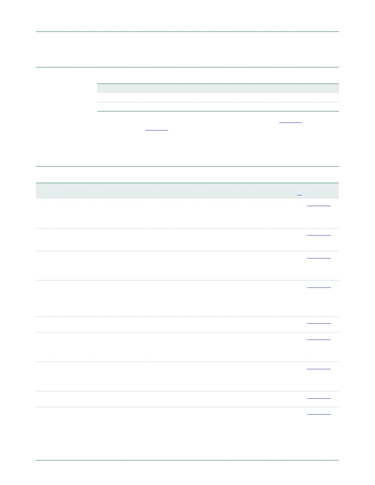
Table 269. I
2
C-bus pin description
Pin Type Description
SDA Input/Output I
2
C Serial Data
SCL Input/Output I
2
C Serial Clock
Table 270. Register overview: I
2
C (base address 0x4000 0000)
Name Access Address
offset
Description Reset
value
[1]
Reference
CONSET R/W 0x000 I2C Control Set Register. When a one is written to a bit of
this register, the corresponding bit in the I
2
C control
register is set. Writing a zero has no effect on the
corresponding bit in the I
2
C control register.
0x00 Table 271
STAT RO 0x004 I2C Status Register. During I
2
C operation, this register
provides detailed status codes that allow software to
determine the next action needed.
0xF8 Table 272
DAT R/W 0x008 I2C Data Register. During master or slave transmit mode,
data to be transmitted is written to this register. During
master or slave receive mode, data that has been received
may be read from this register.
0x00 Table 273
ADR0 R/W 0x00C I2C Slave Address Register 0. Contains the 7-bit slave
address for operation of the I
2
C interface in slave mode,
and is not used in master mode. The least significant bit
determines whether a slave responds to the General Call
address.
0x00 Table 274
SCLH R/W 0x010 SCH Duty Cycle Register High Half Word. Determines
the high time of the I
2
C clock.
0x04 Table 275
SCLL R/W 0x014 SCL Duty Cycle Register Low Half Word. Determines
the low time of the I
2
C clock. I2nSCLL and I2nSCLH
together determine the clock frequency generated by an
I
2
C master and certain times used in slave mode.
0x04 Table 276
CONCLR WO 0x018 I2C Control Clear Register. When a one is written to a bit
of this register, the corresponding bit in the I
2
C control
register is cleared. Writing a zero has no effect on the
corresponding bit in the I
2
C control register.
NA Table 278
MMCTRL R/W 0x01C Monitor mode control register. 0x00 Table 279
ADR1 R/W 0x020 I2C Slave Address Register 1. Contains the 7-bit slave
address for operation of the I
2
C interface in slave mode,
and is not used in master mode. The least significant bit
determines whether a slave responds to the General Call
address.
0x00 Table 280

 Loading...


