UM10462 All information provided in this document is subject to legal disclaimers. © NXP B.V. 2016. All rights reserved.
User manual Rev. 5.5 — 21 December 2016 305 of 523
NXP Semiconductors
UM10462
Chapter 14: LPC11U3x/2x/1x I2C-bus controller
slave mode. The STA, STO and SI bits must be 0. The SI Bit is cleared by writing 1 to the
SIC bit in the CONCLR register. THe STA bit should be cleared after writing the slave
address.
The first byte transmitted contains the slave address of the receiving device (7 bits) and
the data direction bit. In this mode the data direction bit (R/W) should be 0 which means
Write. The first byte transmitted contains the slave address and Write bit. Data is
transmitted 8 bits at a time. After each byte is transmitted, an acknowledge bit is received.
START and STOP conditions are output to indicate the beginning and the end of a serial
transfer.
The I
2
C interface will enter master transmitter mode when software sets the STA bit. The
I
2
C logic will send the START condition as soon as the bus is free. After the START
condition is transmitted, the SI bit is set, and the status code in the STAT register is 0x08.
This status code is used to vector to a state service routine which will load the slave
address and Write bit to the DAT register, and then clear the SI bit. SI is cleared by writing
a 1 to the SIC bit in the CONCLR register.
When the slave address and R/W bit have been transmitted and an acknowledgment bit
has been received, the SI bit is set again, and the possible status codes now are 0x18,
0x20, or 0x38 for the master mode, or 0x68, 0x78, or 0xB0 if the slave mode was enabled
(by setting AA to 1). The appropriate actions to be taken for each of these status codes
are shown in Table 287
to Table 292.
14.9.2 Master Receiver mode
In the master receiver mode, data is received from a slave transmitter. The transfer is
initiated in the same way as in the master transmitter mode. When the START condition
has been transmitted, the interrupt service routine must load the slave address and the
data direction bit to the I
2
C Data register (DAT), and then clear the SI bit. In this case, the
data direction bit (R/W) should be 1 to indicate a read.
Table 283. CONSET used to configure Master mode
Bit 7 6 5 4 3 2 1 0
Symbol - I2EN STA STO SI AA - -
Value- 10000- -
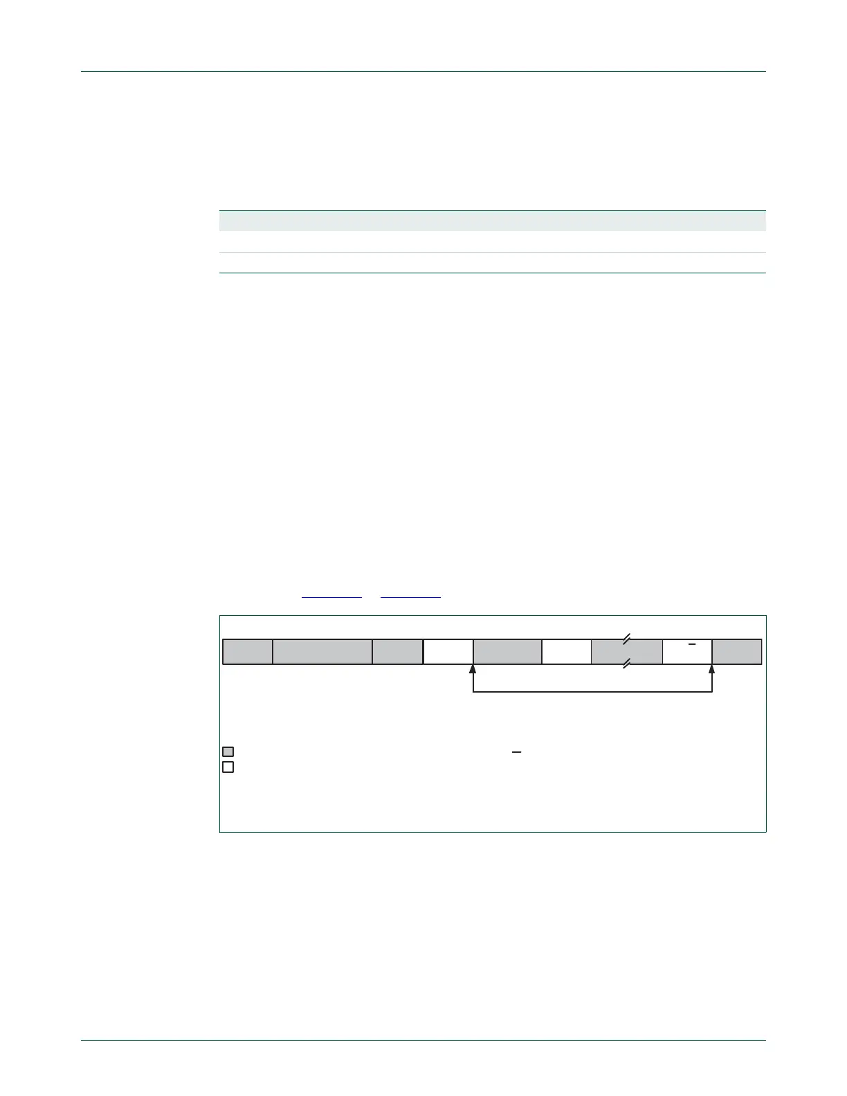
Fig 44. Format in the Master Transmitter mode
A = Acknowledge (SDA low)
A = Not acknowledge (SDA high)
S = START condition
P = STOP condition
S SLAVE ADDRESS RW=0 A DATA A
A/A
P
from Master to Slave
from Slave to Master
DATA
n bytes data transmitted

 Loading...


