UM10462 All information provided in this document is subject to legal disclaimers. © NXP B.V. 2016. All rights reserved.
User manual Rev. 5.5 — 21 December 2016 307 of 523
NXP Semiconductors
UM10462
Chapter 14: LPC11U3x/2x/1x I2C-bus controller
mode. After the address and direction bit have been received, the SI bit is set and a valid
status code can be read from the Status register (STAT). Refer to Table 291
for the status
codes and actions.
14.9.4 Slave Transmitter mode
The first byte is received and handled as in the slave receiver mode. However, in this
mode, the direction bit will be 1, indicating a read operation. Serial data is transmitted via
SDA while the serial clock is input through SCL. START and STOP conditions are
recognized as the beginning and end of a serial transfer. In a given application, I
2
C may
operate as a master and as a slave. In the slave mode, the I
2
C hardware looks for its own
slave address and the General Call address. If one of these addresses is detected, an
interrupt is requested. When the microcontrollers wishes to become the bus master, the
hardware waits until the bus is free before the master mode is entered so that a possible
slave action is not interrupted. If bus arbitration is lost in the master mode, the I
2
C
interface switches to the slave mode immediately and can detect its own slave address in
the same serial transfer.
14.10 Details of I
2
C operating modes
The four operating modes are:
• Master Transmitter
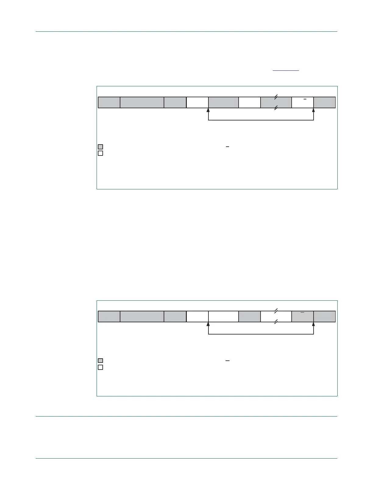
Fig 47. Format of Slave Receiver mode
A
A = Acknowledge (SDA low)
A = Not acknowledge (SDA high)
S = START condition
P = STOP condition
Sr = Repeated START condition
A
A/A
n bytes data received
from Master to Slave
from Slave to Master
S SLAVE ADDRESS RW=0 DATA P/SrDATA
Fig 48. Format of Slave Transmitter mode
DATA
A = Acknowledge (SDA low)
A = Not acknowledge (SDA high)
S = START condition
P = STOP condition
A DATA
n bytes data transmitted
from Master to Slave
from Slave to Master
S SLAVE ADDRESS RW=1 A P
A

 Loading...


