UM10462 All information provided in this document is subject to legal disclaimers. © NXP B.V. 2016. All rights reserved.
User manual Rev. 5.5 — 21 December 2016 379 of 523
18.1 How to read this chapter
The system tick timer (SysTick timer) is part of the ARM Cortex-M0 core and is identical
for all LPC11U3x/2x/1x.
18.2 Basic configuration
The system tick timer is configured using the following registers:
1. Pins: The system tick timer uses no external pins.
2. Power: The system tick timer is enabled through the SysTick control register
(Table 452
). The system tick timer clock is fixed to half the frequency of the system
clock.
3. Enable the clock source for the SysTick timer in the SYST_CSR register (Table 452
).
18.3 Features
• Simple 24-bit timer.
• Uses dedicated exception vector.
• Clocked internally by the system clock or the system clock/2.
18.4 General description
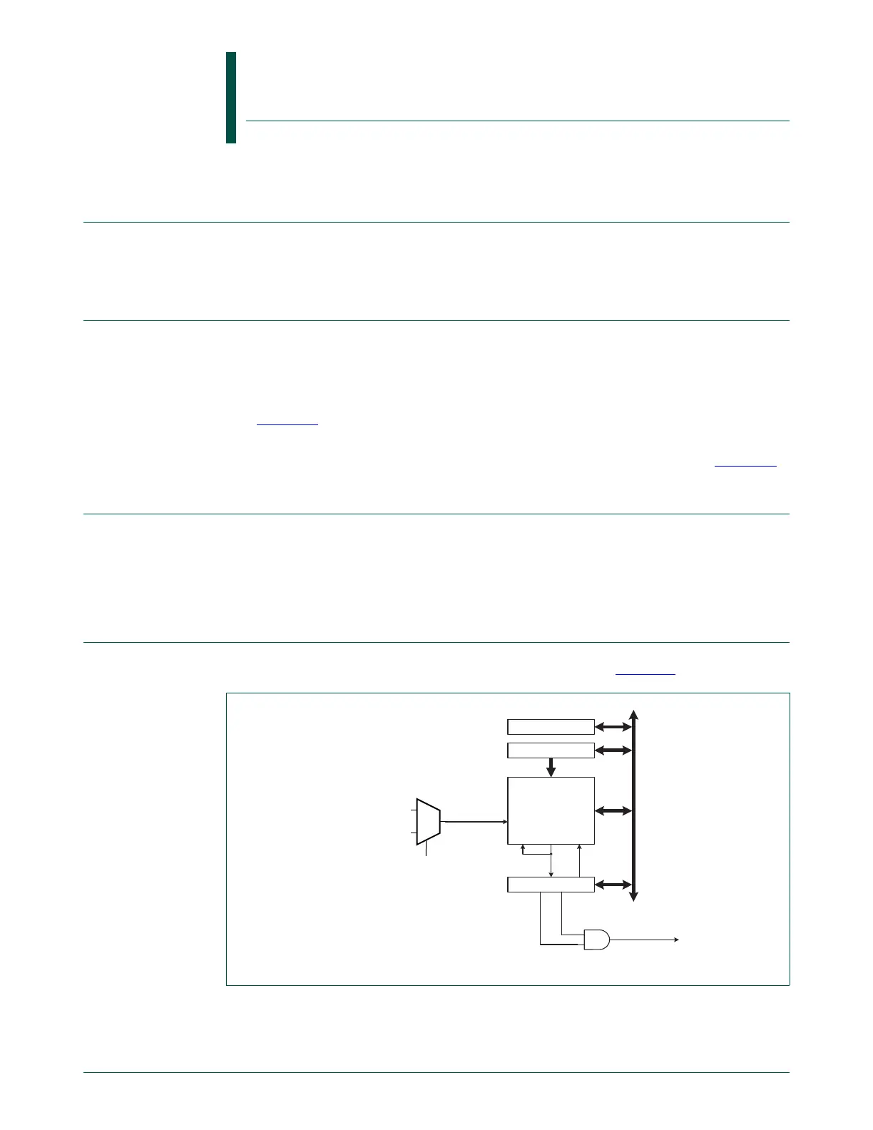
The block diagram of the SysTick timer is shown below in the Figure 68.
The SysTick timer is an integral part of the Cortex-M0. The SysTick timer is intended to
generate a fixed 10 millisecond interrupt for use by an operating system or other system
management software.
UM10462
Chapter 18: LPC11U3x/2x/1x System tick timer
Rev. 5.5 — 21 December 2016 User manual
Fig 68. System tick timer block diagram
system clock
reference clock
= system clock/2
SYST_CALIB
SYST_RVR
SYST_CVR
24-bit down counter
ENABLE
SYST_CSR
private
peripheral
bus
System Tick
interrupt
TICKINTCOUNTFLAG
load
under-
flow
count
enable
clock
load data
1
0
SYST_CSR
bit CLKSOURCE

 Loading...


