UM10462 All information provided in this document is subject to legal disclaimers. © NXP B.V. 2016. All rights reserved.
User manual Rev. 5.5 — 21 December 2016 258 of 523
NXP Semiconductors
UM10462
Chapter 12: LPC11U3x/2x/1x USART
6. The rate counter is loaded into DLM/DLL and the baud rate will be switched to normal
operation. After setting the DLM/DLL, the end of auto-baud interrupt IIR ABEOInt will
be set, if enabled. The RSR will now continue receiving the remaining bits of the
character.
12.5.13 IrDA Control Register
The IrDA Control Register enables and configures the IrDA mode. The value of the ICR
should not be changed while transmitting or receiving data, or data loss or corruption may
occur.
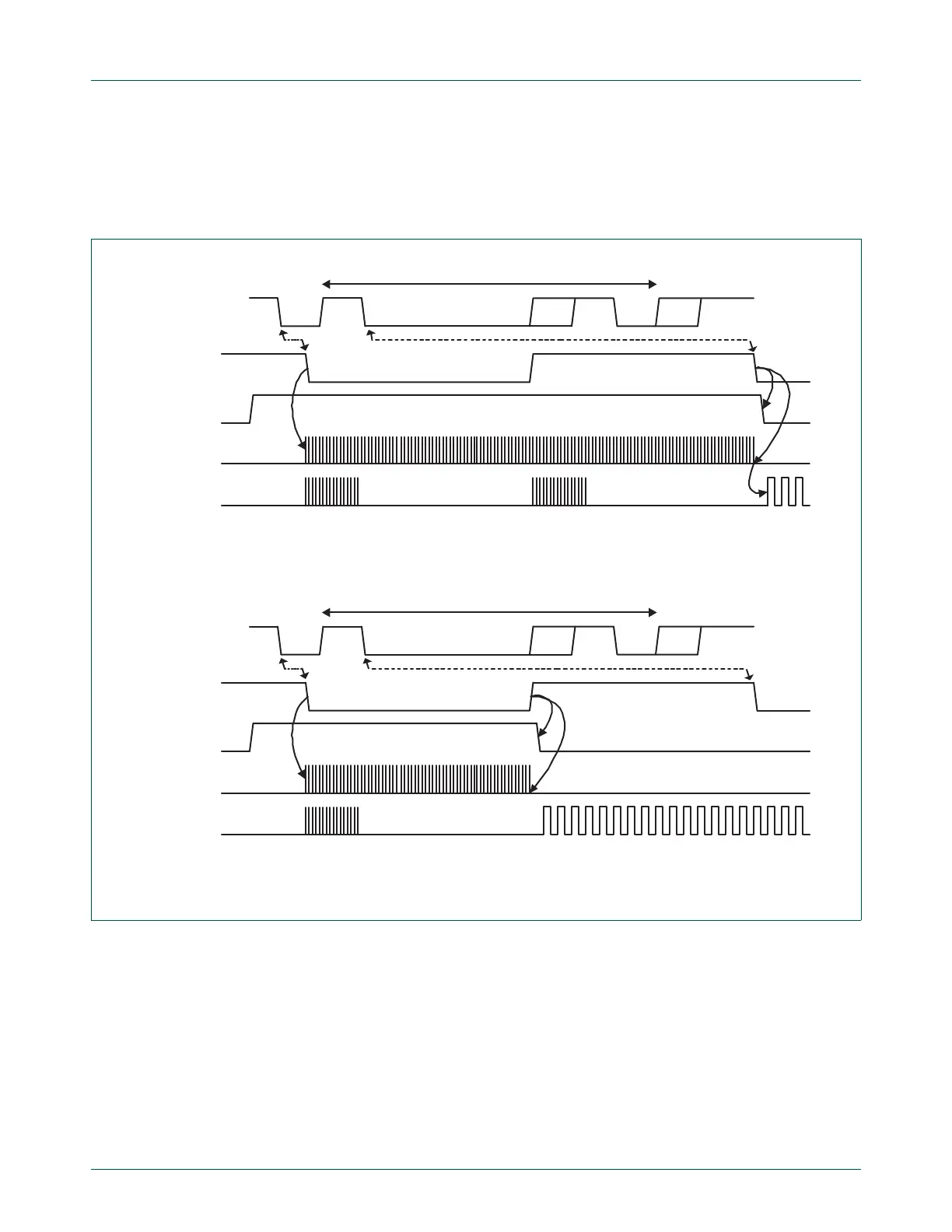
a. Mode 0 (start bit and LSB are used for auto-baud)
b. Mode 1 (only start bit is used for auto-baud)
Fig 27. Auto-baud a) mode 0 and b) mode 1 waveform
UARTn RX
start bit LSB of 'A' or 'a'
U0ACR start
rate counter
start bit0 bit1 bit2 bit3 bit4 bit5 bit6 bit7 parity stop
'A' (0x41) or 'a' (0x61)
16 cycles 16 cycles
16xbaud_rate
UARTn RX
start bit LSB of 'A' or 'a'
rate counter
'A' (0x41) or 'a' (0x61)
start bit0 bit1 bit2 bit3 bit4 bit5 bit6 bit7 parity stop
U1ACR start
16 cycles
16xbaud_rate

 Loading...


