UM10462 All information provided in this document is subject to legal disclaimers. © NXP B.V. 2016. All rights reserved.
User manual Rev. 5.5 — 21 December 2016 14 of 523
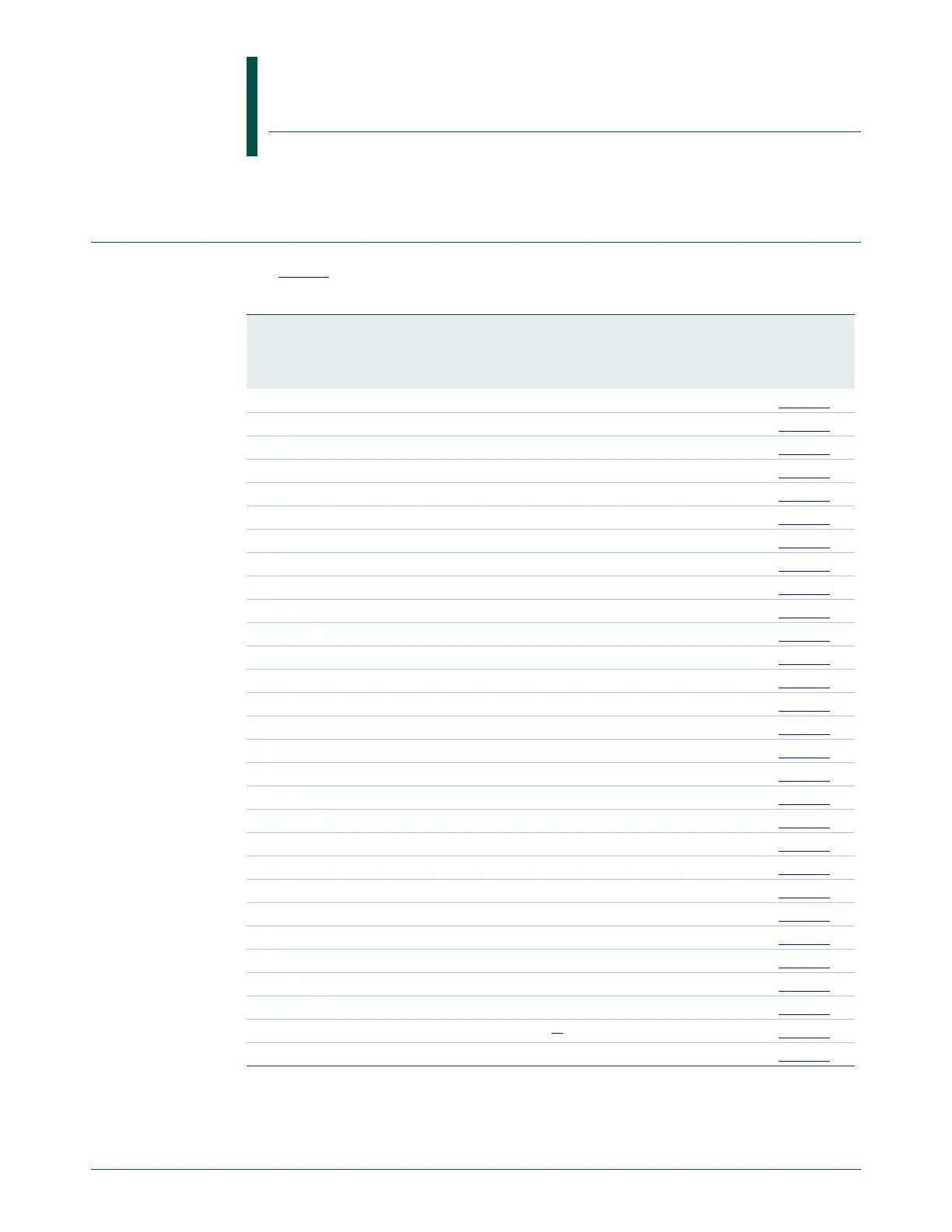
2.1 How to read this chapter
See Table 3 for the memory configuration of the LPC11U3x/2x/1x parts.
[1] For I/O Handler use only.
UM10462
Chapter 2: LPC11U3x/2x/1x Memory mapping
Rev. 5.5 — 21 December 2016 User manual
Table 3. LPC11U3x/2x/1x memory configuration
Part Flash
in kB
Main
SRAM0 at
0x1000
0000
SRAM1 at
0x2000
0000
USB SRAM
at 0x2000
4000
EEPROM Reference
LPC11U12FHN33/201 16 4 - 2 n/a Figure 4
LPC11U12FBD48/201 16 4 - 2 n/a Figure 4
LPC11U13FBD48/201 24 4 - 2 n/a Figure 4
LPC11U14FHN33/201 32 4 - 2 n/a Figure 4
LPC11U14FHI33/201 32 4 - 2 n/a Figure 4
LPC11U14FBD48/201 32 4 - 2 n/a Figure 4
LPC11U14FET48/201 32 4 - 2 n/a Figure 4
LPC11U22FBD48/301 16 6 - 2 1 kB Figure 5
LPC11U23FBD48/301 24 6 - 2 1 kB Figure 5
LPC11U24FHI33/301 32 6 - 2 2 kB Figure 5
LPC11U24FBD48/301 32 6 - 2 2 kB Figure 5
LPC11U24FET48/301 32 6 - 2 2 kB Figure 5
LPC11U24FHN33/401 32 8 - 2 4 kB Figure 5
LPC11U24FBD48/401 32 8 - 2 4 kB Figure 5
LPC11U24FBD64/401 32 8 - 2 4 kB Figure 5
LPC11U34FHN33/311 40 8 - - 4 kB Figure 6
LPC11U34FBD48/311 40 8 - - 4 kB Figure 6
LPC11U34FHN33/421 48 8 - 2 4 kB Figure 6
LPC11U34FBD48/421 48 8 - 2 4 kB Figure 6
LPC11U35FHN33/401 64 8 - 2 4 kB Figure 6
LPC11U35FBD48/401 64 8 - 2 4 kB Figure 6
LPC11U35FBD64/401 64 8 - 2 4 kB Figure 6
LPC11U35FHI33/501 64 8 2 2 4 kB Figure 6
LPC11U35FET48/501 64 8 2 2 4 kB Figure 6
LPC11U36FBD48/401 96 8 - 2 4 kB Figure 6
LPC11U36FBD64/401 96 8 - 2 4 kB Figure 6
LPC11U37FBD48/401 128 8 - 2 4 kB Figure 6
LPC11U37HFBD64/401 128 8 2
[1]
24 kBFigure 6
LPC11U37FBD64/501 128 8 2 2 4 kB Figure 6

 Loading...


