UM10462 All information provided in this document is subject to legal disclaimers. © NXP B.V. 2016. All rights reserved.
User manual Rev. 5.5 — 21 December 2016 244 of 523
NXP Semiconductors
UM10462
Chapter 12: LPC11U3x/2x/1x USART
[1] Reset Value reflects the data stored in used bits only. It does not include reserved bits content.
12.5.1 USART Receiver Buffer Register (when DLAB = 0, Read Only)
The RBR is the top byte of the USART RX FIFO. The top byte of the RX FIFO contains the
oldest character received and can be read via the bus interface. The LSB (bit 0) contains
the first-received data bit. If the character received is less than 8 bits, the unused MSBs
are padded with zeros.
The Divisor Latch Access Bit (DLAB) in the LCR must be zero in order to access the RBR.
The RBR is always Read Only.
Since PE, FE and BI bits (see Table 241
) correspond to the byte on the top of the RBR
FIFO (i.e. the one that will be read in the next read from the RBR), the right approach for
fetching the valid pair of received byte and its status bits is first to read the content of the
LSR register, and then to read a byte from the RBR.
12.5.2 USART Transmitter Holding Register (when DLAB = 0, Write Only)
The THR is the top byte of the USART TX FIFO. The top byte is the newest character in
the TX FIFO and can be written via the bus interface. The LSB represents the first bit to
transmit.
The Divisor Latch Access Bit (DLAB) in the LCR must be zero in order to access the THR.
The THR is always Write Only.
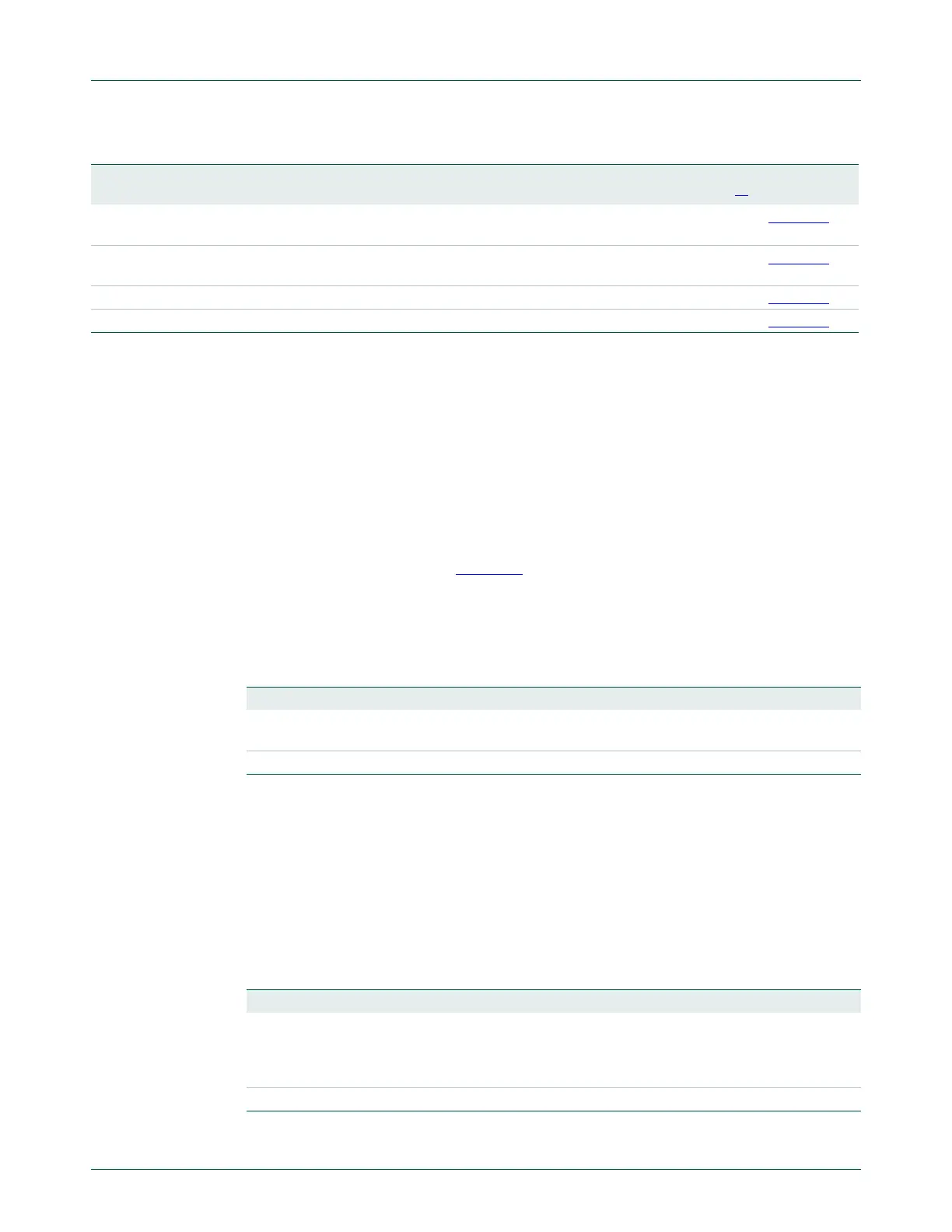
RS485CTRL R/W 0x04C RS-485/EIA-485 Control. Contains controls to
configure various aspects of RS-485/EIA-485 modes.
0 Table 253
RS485ADRMATCH R/W 0x050 RS-485/EIA-485 address match. Contains the
address match value for RS-485/EIA-485 mode.
0 Table 254
RS485DLY R/W 0x054 RS-485/EIA-485 direction control delay. 0 Table 255
SYNCCTRL R/W 0x058 Synchronous mode control register. 0 Table 256
Table 229. Register overview: USART (base address: 0x4000 8000)
Name Access Address
offset
Description Reset
value
[1]
Reference
Table 230. USART Receiver Buffer Register when DLAB = 0, Read Only (RBR - address
0x4000 8000) bit description
Bit Symbol Description Reset Value
7:0 RBR The USART Receiver Buffer Register contains the oldest
received byte in the USART RX FIFO.
undefined
31:8 - Reserved -
Table 231. USART Transmitter Holding Register when DLAB = 0, Write Only (THR - address
0x4000 8000) bit description
Bit Symbol Description Reset Value
7:0 THR Writing to the USART Transmit Holding Register causes the
data to be stored in the USART transmit FIFO. The byte will be
sent when it is the oldest byte in the FIFO and the transmitter is
available.
NA
31:8 - Reserved -

 Loading...


