UM10462 All information provided in this document is subject to legal disclaimers. © NXP B.V. 2016. All rights reserved.
User manual Rev. 5.5 — 21 December 2016 243 of 523
NXP Semiconductors
UM10462
Chapter 12: LPC11U3x/2x/1x USART
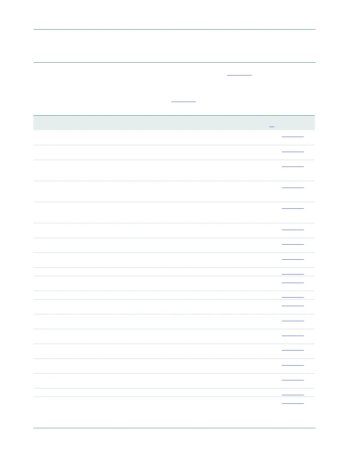
12.5 Register description
The USART contains registers organized as shown in Table 229. The Divisor Latch
Access Bit (DLAB) is contained in the LCR register bit 7 and enables access to the Divisor
Latches.
Offsets/addresses not shown in Table 229
are reserved.
Table 229. Register overview: USART (base address: 0x4000 8000)
Name Access Address
offset
Description Reset
value
[1]
Reference
RBR RO 0x000 Receiver Buffer Register. Contains the next received
character to be read. (DLAB=0)
NA Table 230
THR WO 0x000 Transmit Holding Register. The next character to be
transmitted is written here. (DLAB=0)
NA Table 231
DLL R/W 0x000 Divisor Latch LSB. Least significant byte of the baud
rate divisor value. The full divisor is used to generate
a baud rate from the fractional rate divider. (DLAB=1)
0x01 Table 232
DLM R/W 0x004 Divisor Latch MSB. Most significant byte of the baud
rate divisor value. The full divisor is used to generate
a baud rate from the fractional rate divider. (DLAB=1)
0 Table 233
IER R/W 0x004 Interrupt Enable Register. Contains individual
interrupt enable bits for the 7 potential USART
interrupts. (DLAB=0)
0 Table 234
IIR RO 0x008 Interrupt ID Register. Identifies which interrupt(s) are
pending.
0x01 Table 235
FCR WO 0x008 FIFO Control Register. Controls USART FIFO usage
and modes.
0 Table 236
LCR R/W 0x00C Line Control Register. Contains controls for frame
formatting and break generation.
0 Table 238
MCR R/W 0x010 Modem Control Register. 0 Table 239
LSR RO 0x014 Line Status Register. Contains flags for transmit and
receive status, including line errors.
0x60 Table 241
MSR RO 0x018 Modem Status Register. 0 Table 242
SCR R/W 0x01C Scratch Pad Register. Eight-bit temporary storage for
software.
0 Table 243
ACR R/W 0x020 Auto-baud Control Register. Contains controls for the
auto-baud feature.
0 Table 244
ICR R/W 0x024 IrDA Control Register. Enables and configures the
IrDA (remote control) mode.
0 Table 245
FDR R/W 0x028 Fractional Divider Register. Generates a clock input
for the baud rate divider.
0x10 Table 247
OSR R/W 0x02C Oversampling Register. Controls the degree of
oversampling during each bit time.
0xF0 Table 249
TER R/W 0x030 Transmit Enable Register. Turns off USART
transmitter for use with software flow control.
0x80 Table 250
HDEN R/W 0x040 Half duplex enable register. 0 Table 251
SCICTRL R/W 0x048 Smart Card Interface Control register. Enables and
configures the Smart Card Interface feature.
0 Table 252

 Loading...


