17
F3SG-SR
User’s Manual
Chapter1 Ratings and Specifications
Overview and Specifications
E
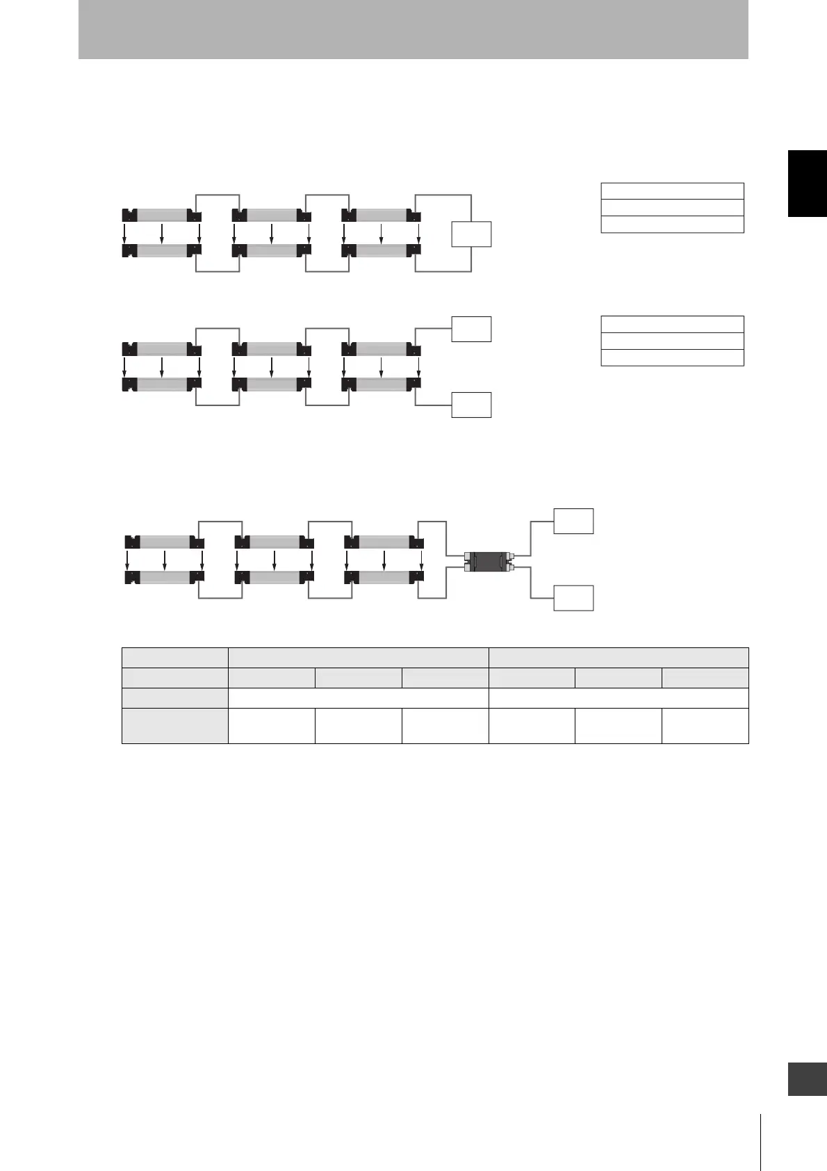
Restrictions on cable extension
The cable extension must satisfy all the following conditions.
<Intellingent Tap not used>
<Intellingent Tap used>
Maximum cable extension (Load condition: Safety outputs 1 and 2: 60 mA, Auxiliary output: 60 mA)
*1. Cable extension when (5) and (6) are 10 m each
*2. (8) must be 20 m max.
*3. Under the maximum load conditions (safety outputs 1 and 2 of 300 mA per channel and auxiliary output of 100 mA), the cable
extension must be 50% max. of the length listed in the table for the F3SG-SRA and 80% max. for the F3SG-SRB.
*4. Conditions exist for the use of the F3SG-SRA in 2-segment or 3-segment cascade. Refer to 1-5-1. F3SG-SR Series –
Electrical – Safety outputs (OSSD).
*5. Not including the Cascading Cable for Extended (F39-JGR3W) and the Root-Plug Cable for Extended (F39-JGR3K).
Sensor F3SG-SRA *1 *3 F3SG-SRB *1 *3
Cascading Single 2-segment *4 3-segment *4 Single 2-segment 3-segment
(1),(2),(3),(4) 10 m each *5 10 m each *5
(5)+(7)
(6)+(7)
≤ 100 m ≤ 70 m ≤ 60 m ≤ 100 m ≤ 95 m ≤ 70 m
- Wired synchronization
* Not including Cascading Cable for Extended (F39-JGR3W) and Root Cable (F39-JGR3K).
- Optical synchronization
Emitter
Receiver
Maximum extionsion length
(1) to (4): 10 m each *
(5) to (6): 100 m each
(1)
(2)
(3)
(4)
(5)
(6)
Emitter
Receiver
(1)
(2)
(3)
(4)
(5)
(6)
Maximum extionsion length
(1) to (4): 10 m each *
(5) to (6): 100 m each
Power
supply
Power
supply
Power
supply
(5)
(6)
(8)*2
(7)
Emitter
Receiver
(1)
(2)
(3)
(4)
Power
supply
IO-Link
master
- Wired synchronization

 Loading...


