Pulse output instructions
1024
Part III FP Instructions
Pulse output (bit 3)
1
0: continue 1: stop
Near home input (bit 2) (see note)
2
0: FALSE 1: TRUE
Count (bit 1)
3
0: permit 1: prohibit
Reset elapsed value to 0 (bit 0)
4
0: no 1: yes
Example: 16#90
Group Value Description
Channel number: 1
Hex 9 corresponds to binary 1001
Pulse output: stop (bit 3) 1
Near home input: FALSE (bit 2) 0
Count: permit (bit 1) 0
II
9
Reset elapsed value to 0: yes (bit 0) 1
I
0 –
Example
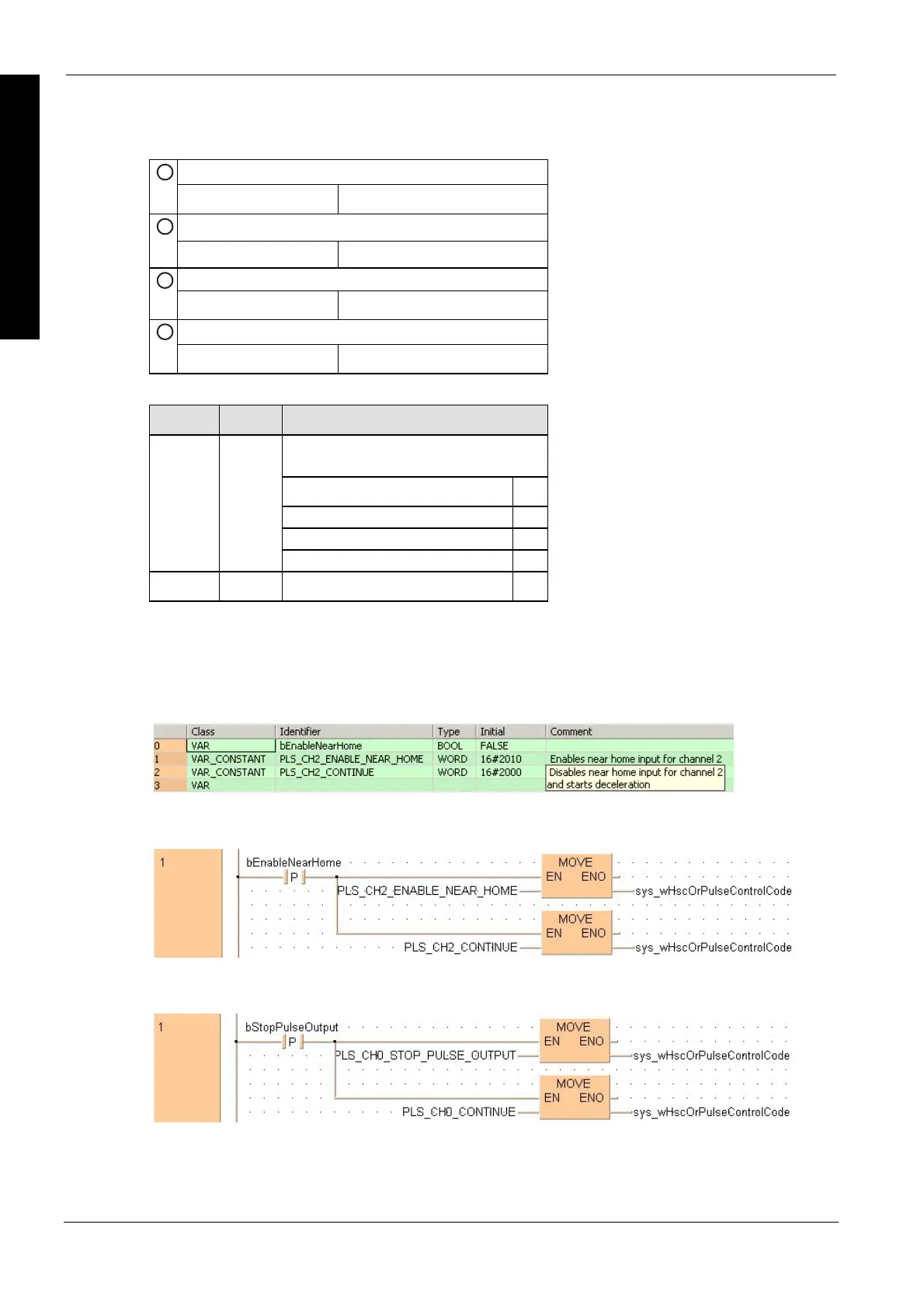
The first example shows how to enable the near home input for channel 2, and the second
example shows how to perform pulse output stop for channel 0.
All input and output variables used for programming this function have been declared in the POU
header.
Body
The near home input is enabled for channel 2 during home return operations.
LD Performing
a forced
stop for
channel 0
(FP0, FP-e,
FP
)
Body
A forced stop of the pulse output is performed for channel 0.
LD

 Loading...


