Analog unit instructions
1117
Part IV Tool Instructions
Input variable Data type Function
iIOWordOffset
INT
The offset of the first WX/WY address of the RTD unit according
to its position.
FP0R, FP0, FP-Sigma: (use
ExpansionUnitToIOWordOffset_FP0 (see page 1128)) or
unit 1 => address 2, unit 2 => address 4, unit 3 => address 6
FP-X: (use Expa
nsionUnotToIOWordOffset_FPX_FP0 (see page
1129)) or
FP0 adapter address of
unit 1
address of
unit 2
address of
unit 3
1st unit 30 32 34
2nd unit 40 42 44
3rd unit 50 52 54
4th unit 60 62 64
5th unit 70 72 72
6th unit 80 82 84
7th unit 90 92 94
8th unit 100 102 104
Output variable
iChannel0–iChannel7
input values on the corresponding output channel (0–3 for
FP0-TC4, channel0–7 for FP0-TC8):
Range K, J type (-100,1°C to 500,1°C->-1001 to 5001 or
-148,1°F to 790,1°F -> -1481 to 7901)
Range T type: (-100,1°C to 400,1°C -> -1001 to 4001 or -148,1°F
to 752,1°F -> -1481 to 7521)
Range R type: (0°C to 1500,1°C -> 0 to 15001 or 32°F to
1590,1°F -> 320 to 15901)
8000 (when the thermocouple is broken)
This function block reads the analog input data from the FP0-TC4 (TC8) unit and stores the digital
values in the corresponding ínput channels:
Range °C values digital values °F values digital values
K, J Type -100.1–500.1 -1001–5001 -148.1–790.1 -1481–7901
T Type -100.1–400.1 -1001–4001 -148.1–752.1 -1481–7521
R Type 0–1500.1 0–15001 32–1590.1 320–15901
8000 when the thermocouple is broken
Data types
Example
In this example the function has been programmed in ladder diagram (LD) and structured text
(ST).The same POU header is used for all programming languages.
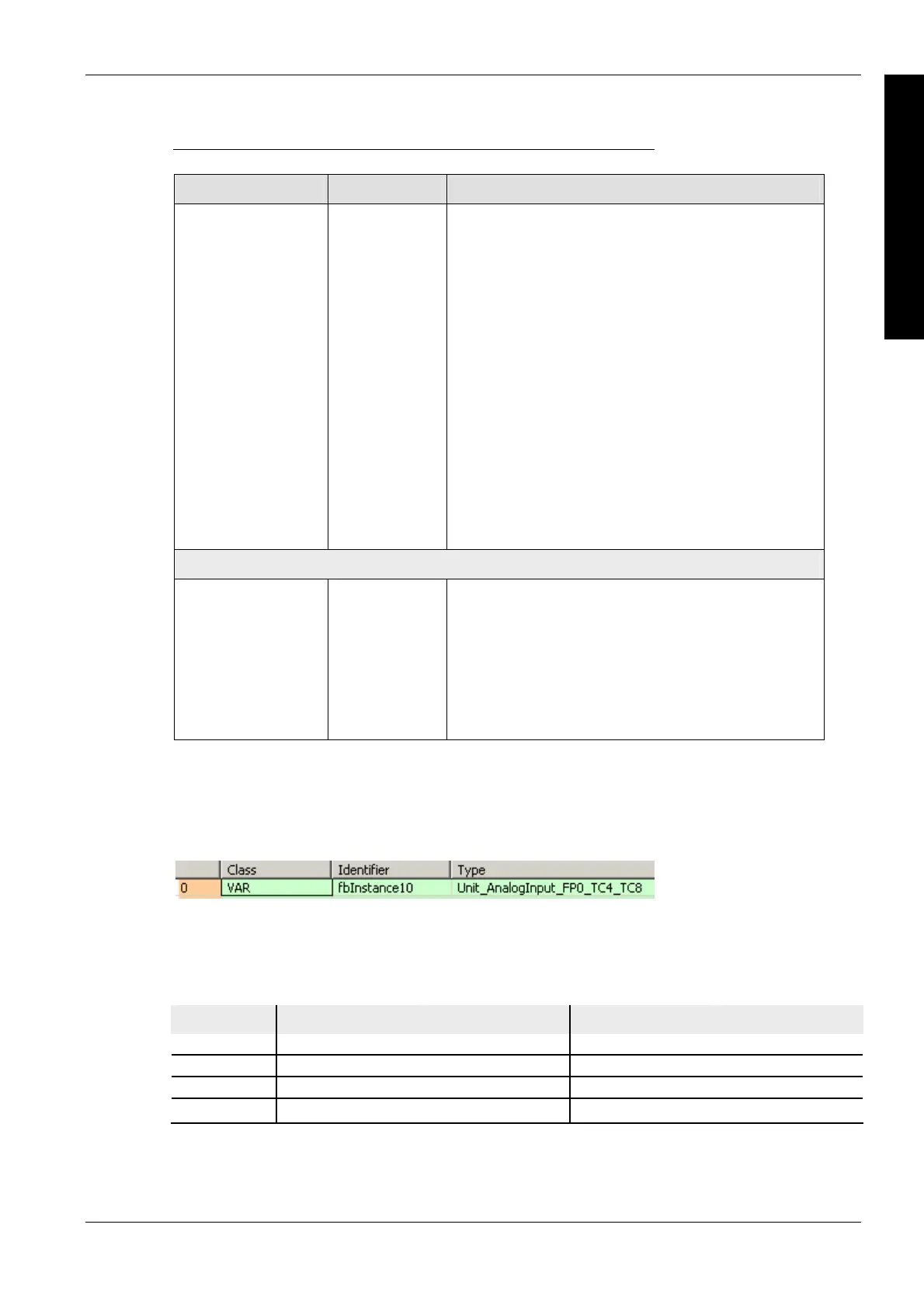
POU header
All input and output variables used for programming this function have been declared in the POU
header.
Body
Use ExpansionUnitNumberToIOWordOffset_FP0 (see page 1125) to calculate the word offset of
the analog unit connected to an FP0.

 Loading...


