EasyManuals Logo

Panasonic FP Series User Manual

Panasonic FP Series
1345 pages
To Next Page IconTo Next Page
To Previous Page IconTo Previous Page
Page #983 background imageLoading...
Page #983 background image
System register instructions
982
Part III FP Instructions
Example:
SYS1 'COM1No,D9999' indicates DT9999
SYS1 'COM1No,D0000' indicates DT0
A calculation error occurs if any value except 1–99 is assigned to the DT memory.
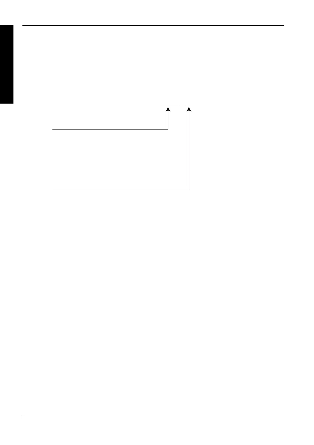
4. Header and Terminator (Shared by the COM 1 and COM 2 ports)
Port used
COM1: COM1 port
COM2: COM2 port
Header
Terminator
STX
STX: STX
NOSTX: no STX
ETX: ETX
CR: CR
CRLF: CR + LF
NOTERM: None
COM1 ,

Table of Contents

Other manuals for Panasonic FP Series

Questions and Answers:

Question and Answer IconNeed help?

Do you have a question about the Panasonic FP Series and is the answer not in the manual?

Panasonic FP Series Specifications

General IconGeneral
MountingDIN rail
TypePLC
Communication InterfaceRS-232, RS-485, Ethernet (depending on model)
Input Voltage100-240V AC or 24V DC (depending on model)
Output TypeRelay, Transistor
I/O PointsVaries by model
Operating Temperature0°C to 55°C
DimensionsVaries by model
WeightVaries by model

Related product manuals